This paper elaborates on the cone crusher upper frame, a foundational structural component located in the upper section of the crusher, which supports key assemblies like the fixed cone, adjustment ring, and feed hopper. Its main functions include structural support (bearing loads up to hundreds of tons and transferring them), forming the crushing chamber (cooperating with the moving cone), ensuring component alignment, and protecting internal parts.
The upper frame, a large hollow cylindrical or conical casting, consists of components such as the frame body (made of high-strength cast steel ZG310–570 or ductile iron QT600–3), fixed cone mounting surface, adjustment ring guide, flange connections (top and bottom flanges), reinforcing ribs, lubrication and inspection ports, and optional cooling jacket, each with specific structural features.
The casting process of the upper frame involves material selection, pattern making (with shrinkage allowances and draft angles), molding (using green sand or resin-bonded sand molds), melting and pouring (with controlled temperatures and flow rates), cooling and shakeout, and heat treatment (normalization and tempering for cast steel, annealing for ductile iron). Its machining and manufacturing process includes rough machining, intermediate heat treatment, finish machining (of flanges, internal taper, and adjustment ring guide), and surface treatment.
Quality control processes cover casting quality inspection (ultrasonic and magnetic particle testing), dimensional accuracy checks (using CMM and laser tracker), material testing (chemical composition and hardness testing), load testing, and assembly fit verification. These processes ensure the upper frame has sufficient structural integrity and dimensional precision to guarantee stable operation of the cone crusher in heavy-duty applications
Detailed Introduction to the Cone Crusher Upper Frame Component
1. Function and Role of the Upper Frame
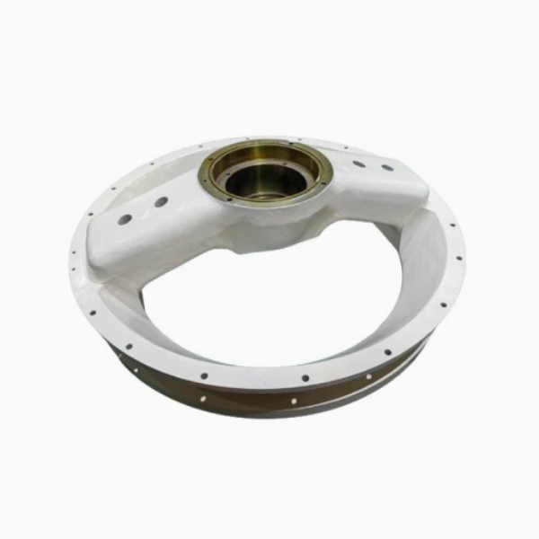
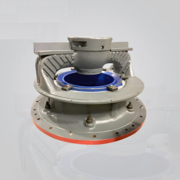
The cone crusher upper frame (also known as the top frame or upper shell) is a foundational structural component located at the upper section of the crusher, serving as the main support for key assemblies such as the fixed cone, adjustment ring, and feed hopper. Its primary functions include:
Structural Support: Bearing the weight of the fixed cone liner, adjustment ring, and incoming material load (up to hundreds of tons), transferring these loads to the lower frame or foundation.
Crushing Chamber Formation: Working in conjunction with the moving cone to form the upper section of the crushing chamber, defining the initial material entry space and guiding ore into the crushing zone.
Component Alignment: Maintaining precise positioning of the fixed cone and adjustment ring relative to the moving cone, ensuring stable crushing gap control and uniform particle size output.
Protection: Enclosing internal components (e.g., eccentric assembly, gears) to shield them from external impacts, dust, and environmental damage.
Given its role in heavy-load bearing and structural stability, the upper frame must 具备 high rigidity, impact resistance, and dimensional accuracy.
2. Composition and Structure of the Upper Frame
The upper frame is a large, hollow, cylindrical or conical casting with complex internal and external features, consisting of the following key components:
Frame Body: The main structural section, typically with a tapered or stepped cylindrical shape, made of high-strength cast steel (e.g., ZG310–570) or ductile iron (QT600–3) for large-sized crushers. Its wall thickness ranges from 50 to 150 mm, with thicker sections at load-bearing areas.
Fixed Cone Mounting Surface: A precision-machined internal conical surface (taper angle 15°–30°) that mates with the fixed cone liner, featuring bolt holes or dovetail grooves for secure attachment.
Adjustment Ring Guide: An external cylindrical or threaded surface that interfaces with the adjustment ring, allowing rotational adjustment of the fixed cone to modify the crushing gap. Threaded guides use trapezoidal threads (metric or inch) for smooth, load-bearing movement.
Flange Connections:
Top Flange: A peripheral flange at the upper end to secure the feed hopper, with evenly spaced bolt holes (M20–M36) and a machined sealing surface to prevent material leakage.
Bottom Flange: A lower flange that connects to the lower frame or base, featuring heavy-duty bolts (grade 8.8 or 10.9) and dowel pins for alignment, ensuring concentricity with the main shaft.
Reinforcing Ribs: Internal and external radial ribs (10–30 mm thick) distributed along the frame body to enhance rigidity, reducing deflection under load (typically limited to ≤0.5 mm under full load).
Lubrication and Inspection Ports: Drilled holes or cast channels for lubricant delivery to the adjustment ring threads, and access ports for visual inspection of internal components.
Cooling Jacket (Optional): A water-cooled cavity in large crushers to dissipate heat from the crushing chamber, with inlet/outlet ports connected to the cooling system.
3. Casting Process for the Upper Frame
The upper frame is almost exclusively manufactured via sand casting due to its large size and complex geometry, with the following steps:
Material Selection:
High-strength cast steel (ZG310–570) is preferred for its excellent tensile strength (≥570 MPa) and impact toughness (elongation ≥15%), suitable for heavy-load applications. For medium-sized frames, ductile iron (QT600–3) is used for better castability and lower cost.
Pattern Making:
A full-scale pattern is created using polyurethane foam or wood, replicating the frame’s external shape, internal taper, flanges, and ribs. Shrinkage allowances (1.5–2.5%) are added based on material (higher for steel), and draft angles (3°–5°) are included for easy mold removal.
The pattern is reinforced with internal supports to prevent deformation during molding.
Molding:
A two-part (cope and drag) green sand mold or resin-bonded sand mold is prepared, with large sand cores used to form the internal cavity and ribs. The mold surface is coated with a refractory wash (alumina-silica) to improve surface finish and prevent metal penetration into the sand.
Melting and Pouring:
For cast steel: The alloy is melted in an electric arc furnace at 1520–1560°C, with chemical composition controlled to C 0.25–0.35%, Si 0.2–0.6%, and Mn 0.8–1.2% to balance strength and toughness.
Pouring is performed using a large ladle with a bottom-pour mechanism, ensuring a steady flow rate (50–100 kg/s) to fill the mold cavity without turbulence, which can cause porosity or cold shuts. The pouring temperature is 1480–1520°C for steel, 1380–1420°C for ductile iron.
Cooling and Shakeout:
The casting is cooled in the mold for 72–120 hours to minimize thermal stress, then removed via vibration. Sand residues are cleaned using shot blasting (G18 steel grit) to achieve a surface roughness of Ra50–100 μm.
Heat Treatment:
Cast steel frames undergo normalization (850–900°C, air-cooled) to refine grain structure, followed by tempering (600–650°C) to reduce hardness to 180–230 HBW, improving machinability.
Ductile iron frames are annealed at 850–900°C (furnace-cooled) to eliminate carbides and reduce hardness to 190–270 HBW.
4. Machining and Manufacturing Process
Rough Machining:
The cast frame is mounted on a large CNC boring mill or gantry mill to machine the top and bottom flange faces, outer diameter, and reference surfaces, leaving 5–10 mm finishing allowance. This ensures flatness (≤2 mm/m) for subsequent machining.
The internal conical surface (fixed cone mounting) is rough-turned using a CNC lathe with a live tooling axis, ensuring the taper angle is within ±0.5° of design.
Intermediate Heat Treatment:
Stress relief annealing at 600–650°C (air-cooled) is performed to remove residual stresses from rough machining, preventing deformation during finish machining.
Finish Machining:
Flanges: The top and bottom flanges are finish-machined to achieve flatness (≤0.1 mm/m) and perpendicularity to the frame axis (≤0.05 mm/100 mm) using a CNC milling machine. Bolt holes are drilled and tapped to class 6H tolerance, with positional accuracy (±0.2 mm) relative to the frame center.
Internal Taper: The fixed cone mounting surface is finish-turned to a surface roughness of Ra3.2 μm, with taper angle tolerance (±0.1°) and diameter tolerance (±0.2 mm) to ensure proper fit with the fixed cone.
Adjustment Ring Guide: Threaded surfaces (if applicable) are precision-machined using a CNC thread milling machine, with thread pitch tolerance (±0.05 mm) and profile accuracy to ensure smooth adjustment movement.
Surface Treatment:
The external surface is painted with an epoxy primer and polyurethane topcoat (total thickness 100–150 μm) to resist corrosion in outdoor or humid environments.
Machined mating surfaces (flanges, internal taper) are coated with anti-rust oil to prevent oxidation during storage and transportation.
5. Quality Control Processes
Casting Quality Inspection:
Ultrasonic testing (UT) is performed on critical load-bearing areas (flanges, rib joints) to detect internal defects (e.g., shrinkage pores >φ5 mm are rejected).
Magnetic particle testing (MPT) checks for surface cracks in flanges and threaded regions, with any linear defects >1 mm resulting in rejection.
Dimensional Accuracy Checks:
A coordinate measuring machine (CMM) with a large measuring volume verifies key dimensions: overall height (±1 mm), flange flatness, taper angle, and bolt hole positions.
The frame’s concentricity (outer diameter relative to internal taper) is measured using a laser tracker, with tolerance ≤0.1 mm/m.
Material Testing:
Chemical composition analysis (spectrometry) confirms compliance with material standards (e.g., ZG310–570: C ≤0.37%, Mn ≤1.2%).
Hardness testing (Brinell) ensures the frame meets hardness specifications (180–230 HBW for steel, 190–270 HBW for ductile iron).
Load Testing:
A static load test is performed by applying 120% of the rated load to the top flange for 24 hours, with no visible deformation (measured via dial indicators) allowed.
Assembly Fit Verification:
The frame is trial-assembled with the fixed cone, adjustment ring, and feed hopper to verify proper alignment and fit, with gaps between mating surfaces (≤0.1 mm) checked using feeler gauges.
Through these rigorous manufacturing and quality control processes, the upper frame achieves the structural integrity and dimensional precision required to support critical crusher components, ensuring stable and efficient operation in heavy-duty crushing application