This paper provides a detailed overview of the cone crusher pinion, a critical transmission component that meshes with the bull gear to transfer motor power to the eccentric assembly, enabling the moving cone's oscillating motion. It elaborates on the pinion's functions, including power transmission, torque amplification, and precision meshing. The composition and structure are detailed, consisting of gear teeth, shaft body, bearing journals, shoulders/collars, lubrication holes, and keyway/spline, along with their structural characteristics. For large-scale pinions, the casting process is described, covering material selection, pattern making, molding, melting and pouring, cooling and shakeout, heat treatment, and inspection. For forged pinions, the machining and manufacturing process is outlined, including forging, rough machining, heat treatment, finish machining, and deburring/polishing. Additionally, quality control measures are specified, such as material validation, dimensional accuracy checks, hardness and microstructure testing, dynamic performance testing, non-destructive testing, and final inspection. These processes ensure the pinion achieves the required strength, precision, and durability, guaranteeing reliable power transmission in demanding crushing operations
Detailed Introduction to the Cone Crusher Pinion Component
1. Function and Role of the Pinion
The cone crusher pinion (also called the drive pinion or small gear) is a critical transmission component in the crusher’s power system, meshing directly with the large bull gear to transfer rotational energy from the motor to the eccentric assembly. Its key functions include:
Power Transmission: Converting the motor’s high-speed rotation (typically 1450 rpm for electric motors) into the lower-speed, high-torque motion required by the bull gear, driving the oscillating movement of the moving cone.
Torque Amplification: Acting as a speed reducer (gear ratio 5:1 to 8:1) to multiply torque, enabling the crusher to handle hard materials like granite or basalt.
Precision Meshing: Maintaining stable engagement with the bull gear to ensure smooth operation, reducing vibration and noise during crushing.
Due to its role in high-stress, continuous operation, the pinion must balance high strength, wear resistance, and dimensional accuracy to avoid premature failure.
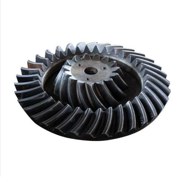
2. Composition and Structure of the Pinion
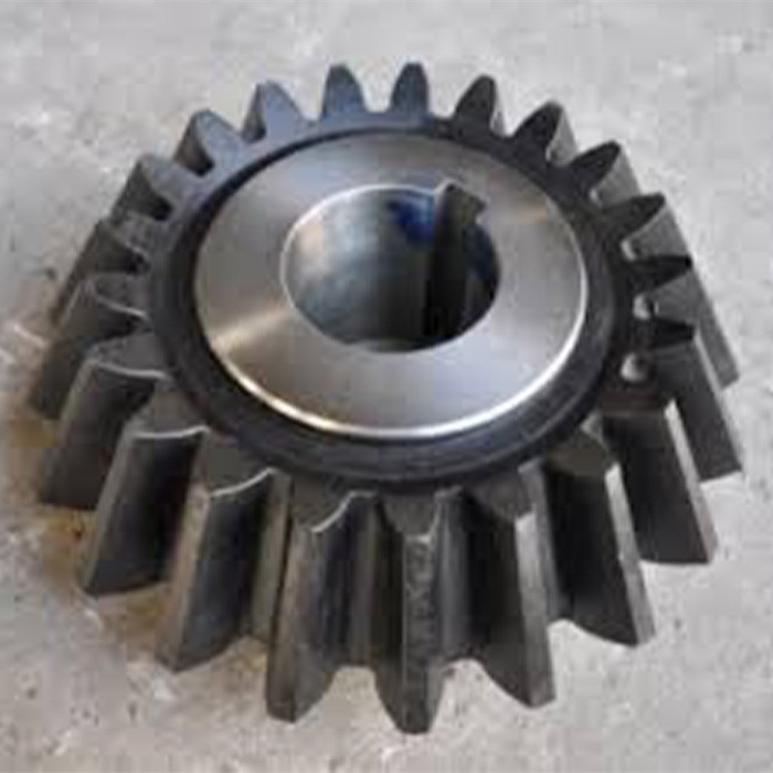
The pinion is a small cylindrical gear with a solid or hollow shaft, featuring the following components and structural details:
Gear Teeth: External involute teeth (modulus 6–16, depending on crusher size) with a pressure angle of 20°,designed to mesh with the bull gear. The tooth profile includes a fillet radius at the root to reduce stress concentration.
Shaft Body: A cylindrical shaft integrated with the gear, with one end connected to the motor via a coupling (e.g., flexible or fluid coupling) and the other supported by bearings (roller or ball bearings). Shaft diameters range from 50 mm to 300 mm, with keyways or splines for torque transmission.
Bearing Journals: Precision-machined cylindrical sections on the shaft where bearings are mounted,with tight tolerances (IT5–IT6) to ensure smooth rotation and minimal runout.
Shoulders or Collars: Axial projections on the shaft that position the bearings and prevent axial movement during operation.
Lubrication Holes: Small drilled holes leading to the gear teeth and bearing journals,delivering oil or grease to reduce friction and wear.
Keyway or Spline: A slot or series of ridges on the shaft end that mates with the motor coupling,ensuring torque transfer without slippage.
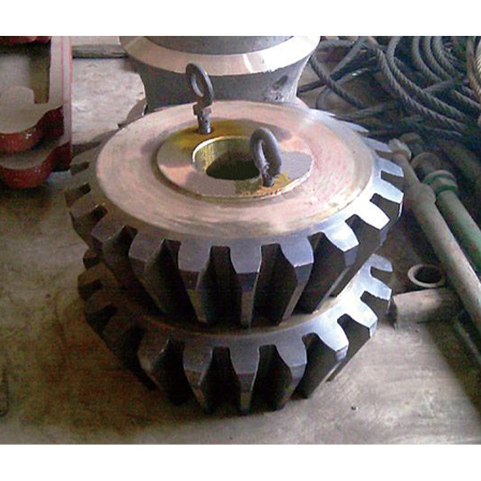
3. Casting Process for the Pinion (for Large-Scale Pinions)
While small pinions are often forged, large pinions (shaft diameter >150 mm) may use casting for cost-effectiveness, with the following steps:
Material Selection:
High-strength alloy cast steel (ZG40CrNiMo) is preferred,offering tensile strength ≥800 MPa and impact toughness ≥60 J/cm² to withstand cyclic loads.
Pattern Making:
A full-scale foam or wood pattern is created,replicating the gear teeth, shaft, and journals. Shrinkage allowances (2–2.5%) are added to account for cooling contraction.
Molding:
Resin-bonded sand molds are formed around the pattern,with a sand core for the hollow shaft (if applicable). The mold cavity is coated with a refractory wash to ensure a smooth surface.
Melting and Pouring:
The alloy is melted in an electric arc furnace at 1550–1600°C,with chemical composition controlled to C 0.38–0.45%,Cr 0.8–1.1%,Ni 1.2–1.5%,and Mo 0.2–0.3%.
Pouring is performed at 1500–1530°C using a bottom-pouring ladle to minimize turbulence,ensuring complete filling of the mold.
Cooling and Shakeout:
The casting is cooled in the mold for 48–72 hours to reduce thermal stress,then removed via vibration. Sand residues are cleaned using shot blasting.
Heat Treatment:
Normalization (880–920°C,air-cooled) refines the grain structure,followed by tempering (600–650°C) to achieve a hardness of 220–250 HBW,improving machinability.
Casting Inspection:
Visual inspection and dye penetrant testing (DPT) check for surface cracks or blowholes.
Ultrasonic testing (UT) detects internal defects,with strict limits (no defects >φ2 mm in gear teeth or shaft core).
4. Machining and Manufacturing Process (Forged Pinions)
Most pinions are forged for higher strength,with the following manufacturing steps:
Forging:
A steel billet (40CrNiMoA) is heated to 1100–1200°C and forged into a rough shaft-gear shape using a hydraulic press,improving grain flow and mechanical properties.
Rough Machining:
The forged blank is turned on a CNC lathe to machine the shaft outer diameter,shoulders,and bearing journals,leaving 2–3 mm finishing allowance.
Gear teeth are rough-cut using a gear hobbing machine,with a 0.5 mm allowance for finishing.
Heat Treatment:
Carburizing: The gear teeth and shaft surface are carburized at 900–930°C for 6–10 hours to create a hard layer (0.8–1.2 mm thick),enhancing wear resistance.
Quenching and Tempering: Oil-quenched to 850–880°C,then tempered at 180–200°C to achieve surface hardness HRC 58–62 (teeth) and core hardness HRC 30–35 (shaft).
Finish Machining:
Gear teeth are ground using a gear grinder to AGMA 7–8 accuracy,with tooth profile deviation ≤0.015 mm and surface roughness Ra0.8 μm.
Bearing journals are precision-ground to IT5 tolerance,with roundness ≤0.005 mm and surface roughness Ra0.4 μm to ensure smooth bearing operation.
Keyways or splines are broached to tight tolerances (width ±0.01 mm) for secure coupling engagement.
Deburring and Polishing:
Tooth edges are deburred using a brush or abrasive wheel to prevent stress concentration.
Lubrication holes are countersunk and polished to avoid oil flow obstruction.
5. Quality Control Processes
Material Validation:
Chemical analysis (spectrometry) confirms alloy composition (e.g.,40CrNiMoA: C 0.37–0.44%,Ni 1.25–1.65%,Mo 0.15–0.25%).
Tensile testing on forged samples verifies yield strength (≥835 MPa) and elongation (≥12%).
Bearing journals are checked for concentricity with the gear axis (≤0.01 mm) using a dial indicator.
Hardness and Microstructure Testing:
Surface hardness of teeth is measured using a Rockwell tester (HRC 58–62 required).
Metallographic analysis ensures uniform carburized layer depth and no excessive retained austenite.
Dynamic Performance Testing:
Meshing test: The pinion is paired with a bull gear on a test rig to measure noise (≤80 dB at rated speed) and vibration (≤0.05 mm/s).
Overload test: Operated at 120% rated torque for 2 hours to check for tooth deformation or bearing overheating.
Non-Destructive Testing (NDT):
Magnetic particle testing (MPT) detects surface cracks in teeth,shaft shoulders,and keyways.
Ultrasonic testing (UT) inspects the shaft core for internal defects (no defects >φ2 mm).
Final Inspection:
A full audit of test reports,including material certificates and dimensional records,is conducted before approval.
The pinion is marked with part number,hardness,and inspection date for traceability.
Through these rigorous processes,the cone crusher pinion achieves the required strength,precision,and durability,ensuring reliable power transmission and long service life in demanding crushing environments