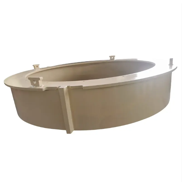
The cone crusher adjustment cap is a key component in the crusher's gap adjustment system, mounted on top of the adjustment ring or upper frame. Its main functions include controlling the crushing gap (enabling precise adjustment of the distance between the moving and fixed cones), locking components (securing the adjustment ring after adjustment), distributing loads, and supporting seals.
Structurally, it is a cylindrical or conical component consisting of the cap body (made of high-strength cast steel like ZG310–570 or forged steel), threaded bore or external threads, locking mechanisms (such as locking slots, set screw holes, and tapered interfaces), top flange, seal grooves, reinforcing ribs, and indicator marks.
The casting process for medium to large adjustment caps involves material selection, pattern making (with shrinkage allowances and draft angles), molding (using sand molds), melting and pouring (with controlled temperatures and flow rates), cooling and shakeout, and heat treatment (normalization and tempering). The machining and manufacturing process includes rough machining, thread machining, locking feature machining, finish machining, surface treatment, and assembly of seals.
Quality control processes cover material validation (chemical composition and hardness testing), dimensional accuracy checks (using CMM and thread gauges), structural integrity testing (NDT like MPT and UT), functional testing (adjustment range and locking effectiveness verification), and seal performance testing. These ensure the adjustment cap has the required precision, strength, and reliability for consistent crushing gap control, guaranteeing optimal crusher performanc
Detailed Introduction to the Cone Crusher Adjustment Cap Component
1. Function and Role of the Adjustment Cap
The cone crusher adjustment cap (also referred to as the adjusting cap or regulating cap) is a key component in the crusher’s gap adjustment system, mounted on top of the adjustment ring or upper frame. Its primary functions include:
Crushing Gap Control: Enabling precise adjustment of the distance between the moving cone and fixed cone (crushing gap) by rotating or translating relative to the adjustment ring, directly influencing the size of the discharged material.
Component Locking: Securing the adjustment ring in its set position after gap adjustment, preventing unintended movement caused by vibration during crushing operations.
Load Distribution: Distributing axial loads from the adjustment ring to the upper frame, reducing localized stress on mating components.
Sealing Support: Providing a mounting surface for seals that prevent dust, debris, or lubricant leakage between the adjustment system and the crusher’s internal mechanisms.
Given its role in precision adjustment and load-bearing, the adjustment cap requires high dimensional accuracy, wear resistance, and structural stability.
2. Composition and Structure of the Adjustment Cap
The adjustment cap is typically a cylindrical or conical component with a combination of threaded, flanged, and smooth surfaces, consisting of the following key parts:
Cap Body: The main structural section, usually made of high-strength cast steel (e.g., 40Cr or ZG310–570) or forged steel for enhanced durability. Its wall thickness ranges from 30 to 80 mm, with thicker sections at load-bearing interfaces.
Threaded Bore or External Threads: A central threaded feature that mates with the adjustment ring—either internal threads (for caps that screw onto the adjustment ring) or external threads (for caps that are secured by a locking nut). Threads are often trapezoidal (metric or inch) to handle high axial loads.
Locking Mechanism: Features to secure the cap after adjustment, such as:
Locking Slots: Circumferential grooves around the cap’s outer surface that align with locking bolts on the adjustment ring, preventing rotation.
Set Screw Holes: Radial threaded holes that accept set screws to press against the adjustment ring, creating friction-based locking.
Tapered Interface: A conical surface that mates with a corresponding taper on the adjustment ring, enhancing grip under load.
Top Flange: A radial flange at the upper end of the cap, providing a surface for applying torque during adjustment (via a wrench or hydraulic tool) and limiting axial movement.
Seal Grooves: Circumferential grooves on the outer or inner surface that house O-rings, gaskets, or labyrinth seals to prevent contamination or lubricant loss.
Reinforcing Ribs: Internal or external ribs (5–15 mm thick) that strengthen the cap body, particularly around threaded areas, to resist deformation under load.
Indicator Marks: Engraved or stamped lines on the outer surface that align with reference marks on the adjustment ring, facilitating precise gap adjustment (typically graduated in 0.1 mm increments).
3. Casting Process for the Adjustment Cap
For medium to large adjustment caps, casting is the preferred manufacturing method due to its ability to produce complex shapes efficiently:
Material Selection:
High-strength cast steel (ZG310–570) is chosen for its tensile strength (≥570 MPa) and impact toughness, suitable for load-bearing applications. For smaller caps, ductile iron (QT500–7) may be used for cost-effectiveness, offering good machinability.
Pattern Making:
A precision pattern is created using wood, foam, or 3D-printed plastic, replicating the cap’s external shape, threads (in simplified form), flanges, and grooves. Shrinkage allowances (1.5–2%) are added, with draft angles (2°–4°) to ease mold removal.
Thread patterns are often omitted or simplified in the casting, with final threading achieved via machining.
Molding:
A sand mold (green sand or resin-bonded sand) is formed around the pattern, with a core used to create the central bore. The mold cavity is coated with a refractory wash to improve surface finish and prevent metal penetration into the sand.
Melting and Pouring:
Cast steel is melted in an electric arc furnace at 1520–1560°C, with chemical composition controlled to C 0.25–0.35%, Mn 0.8–1.2%, and Si 0.2–0.6% to balance strength and machinability.
Pouring is performed at 1480–1520°C using a ladle, with a steady flow rate to avoid turbulence, ensuring complete filling of the mold cavity.
Cooling and Shakeout:
The casting is cooled in the mold for 24–48 hours to reduce thermal stress, then removed via vibration. Sand residues are cleaned using shot blasting (G25 steel grit), achieving a surface roughness of Ra25–50 μm.
Heat Treatment:
Normalization (850–900°C, air-cooled) refines the grain structure, followed by tempering (600–650°C) to reduce hardness to 200–250 HBW, improving machinability while maintaining strength.
4. Machining and Manufacturing Process
Rough Machining:
The cast blank is mounted on a CNC lathe to machine the outer diameter, top flange, and central bore, leaving 2–3 mm finishing allowance. Key surfaces are faced to establish reference datums.
Thread Machining:
Internal or external threads are precision-machined using a CNC thread lathe or thread milling machine. Trapezoidal threads are cut with a form tool, ensuring pitch accuracy (±0.05 mm) and thread profile tolerance to enable smooth adjustment.
Locking Feature Machining:
Locking slots are milled into the outer surface using a CNC milling machine, with depth tolerance (±0.1 mm) and uniform spacing (±0.5 mm) around the cap’s circumference.
Set screw holes are drilled and tapped to class 6H tolerance, with perpendicularity (±0.1 mm/100 mm) relative to the cap’s axis to ensure proper screw engagement.
Finish Machining:
The top flange and sealing surfaces are finish-turned to achieve flatness (≤0.05 mm/m) and surface roughness Ra1.6 μm, ensuring effective sealing and torque application.
Tapered interfaces (if applicable) are machined to an angle tolerance (±0.1°) and surface roughness Ra3.2 μm for secure mating with the adjustment ring.
Surface Treatment:
The cap’s outer surface is coated with anti-rust paint or zinc plating (5–8 μm thick) to resist corrosion. Threads are treated with anti-seize compound (e.g., molybdenum disulfide) to facilitate smooth adjustment and prevent galling.
Assembly of Seals:
O-rings or gaskets are installed in seal grooves, with dimensions matched to the groove width and depth to ensure a tight seal under compression.
5. Quality Control Processes
Material Validation:
Chemical composition analysis (via spectrometry) confirms the base material meets specifications (e.g., 40Cr: C 0.37–0.44%, Cr 0.8–1.1%).
Hardness testing (Brinell or Rockwell) verifies the cap body has a hardness of 200–250 HBW, ensuring a balance of strength and machinability.
Thread quality is assessed using thread gauges (ring or plug gauges) to ensure proper fit with the adjustment ring.
Structural Integrity Testing:
Non-destructive testing (NDT) such as magnetic particle testing (MPT) detects surface cracks in threads, flanges, or locking features, with any defects >0.5 mm in length rejected.
Ultrasonic testing (UT) is performed on large caps to check for internal defects (e.g., shrinkage pores) in load-bearing regions.
Functional Testing:
Adjustment range verification: The cap is mated with a test adjustment ring, and its rotation/translation range is measured to ensure it covers the design gap range (typically 5–50 mm).
Locking effectiveness test: After setting the cap to a mid-range position, a vibration test (10–500 Hz for 1 hour) is conducted, with no measurable movement (≤0.01 mm) allowed.
Seal Performance Testing:
A pressure test is performed by mounting the cap with seals on a test fixture and applying 0.3 MPa air pressure, with no leakage detected via soap solution inspection.
By adhering to these processes, the adjustment cap achieves the precision, strength, and reliability required to maintain consistent crushing gap control, ensuring optimal crusher performance and product quality in mining and aggregate processing applications