This paper details the ball mill feed end cover, a key component connecting the cylinder and feeding device, which guides materials into the cylinder, seals the cylinder end to prevent dust leakage, and forms a support structure with the hollow shaft. It requires strength and toughness, with Q235B and Q355B steel as common materials, featuring a disc or flanged structure with a central feed port and internal wear-resistant screw blades. The manufacturing process of large Q355B end covers is elaborated, including raw material pretreatment, cutting, forming, rough machining, welding (with post-heat treatment), finish machining (flange surface and feed port processing), and surface treatment. Comprehensive inspection procedures are also outlined, covering raw materials (chemical composition, mechanical properties), welding quality (non-destructive testing), dimensional accuracy (flange flatness, hole position tolerance), and final assembly compatibility and sealing performance tests. These ensure the feed end cover meets operational requirements, with a service life of 8-10 years, supporting stable feeding and sealed operation of the ball mill.
Detailed Introduction, Manufacturing Process, and Inspection Process of Ball Mill Feed End Covers
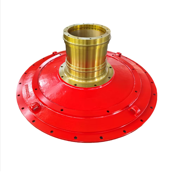
I. Functions and Structural Features of Feed End Covers
The ball mill feed end cover is a key component connecting the cylinder and the feeding device, located at the feed end of the cylinder. Its main functions include receiving and guiding materials into the cylinder, sealing the cylinder end to prevent dust leakage, and forming a stable support structure with the hollow shaft, while withstanding feed impact and partial cylinder loads. Its performance directly affects the feeding efficiency and operational tightness of the ball mill.
Core Functions:
Material guiding: Through the internal feed screw or conical structure, uniformly introduce externally conveyed materials into the cylinder to avoid local accumulation;
Sealing protection: Cooperate with sealing devices (e.g., labyrinth seals, felt seals) to prevent dust and grinding media from leaking out of the cylinder;
Structural support: As a closure for the cylinder end, it is welded or bolted to the hollow shaft to jointly bear radial and axial forces of the cylinder.
Structural Features:
Shape: Mostly disc-shaped or special-shaped with flanges, with a central feed port (connected to the hollow shaft inner hole) and a flange at the edge for bolted connection to the cylinder;
Material: Requires both strength and toughness. Small and medium-sized ball mills commonly use Q235B carbon steel, while large or heavy-duty models adopt Q355B low-alloy steel (yield strength ≥355MPa). The wall thickness is typically 20-60mm depending on the diameter;
Design details: The inner side is often welded with feed screw blades (material ZGMn13 for wear resistance), and the outer side is machined with a step surface (roughness Ra≤3.2μm) matching the sealing device.
II. Manufacturing Process of Feed End Covers (Taking Large Q355B End Covers as an Example)
1. Raw Material Pretreatment and Cutting
Raw material selection: Use Q355B steel plates with a thickness of 20-60mm, accompanied by material certificates (chemical composition: C≤0.20%, Mn 1.2-1.6%, Si≤0.55%). Mechanical properties (tensile strength 470-630MPa, elongation ≥20%) must be verified;
Cutting:
Cut according to the expanded size of the end cover (including flange edges) using CNC flame cutting. The perpendicularity of the cutting surface is ≤1mm/m, with no cracks or burrs on the edges (checked with a 10x magnifier);
Reserve a 5-10mm machining allowance for the central feed port, and pre-mark the positions of flange bolt holes.
2. Forming and Rough Machining
Forming:
Small and medium-sized end covers can be directly formed by CNC cutting; large end covers (diameter ≥3m) require local heating of the steel plate to 300-400℃ and pressing with a press to avoid cold working deformation;
Rough turning:
Roughly turn the end face and flange joint surface on a CNC vertical lathe, leaving a 3-5mm finishing allowance;
Roughly bore the central feed port, with a 2-3mm grinding allowance for the diameter, and control the inner hole surface roughness to Ra≤12.5μm.
3. Welding and Heat Treatment (Key Processes)
Component welding:
If the end cover needs to be welded with feed screws or reinforcing ribs, use submerged arc automatic welding (wire H08MnA, flux HJ431) with a welding current of 500-600A and voltage of 28-32V. Ensure the weld leg height is ≥8mm;
Immediately perform post-weld heat treatment at 250-300℃ for 2 hours after welding to eliminate welding stress and prevent cracks;
Overall quenching and tempering (optional for large end covers):
For end covers bearing heavy loads, heat to 850-870℃, air-cool after insulation (normalizing) to refine grains, and control hardness to 180-230HBW to ensure machinability.
4. Finish Machining
Finish turning the flange surface:
Finish turn the flange surface connected to the cylinder on a CNC vertical lathe, with flatness ≤0.05mm/m and surface roughness Ra≤3.2μm, ensuring tight fitting with the cylinder flange (gap ≤0.1mm);
Machine flange bolt holes (12-36 holes depending on diameter, aperture φ20-φ50mm) with a positional tolerance of ±0.1mm and cumulative hole distance error ≤0.2mm;
Finish boring the feed port:
Finish bore the inner hole of the central feed port, with the tolerance of the part matching the hollow shaft controlled to H7 (e.g., a φ300mm inner hole allows +0.03-+0.07mm) and surface roughness Ra≤1.6μm;
Machine the sealing step surface (matching the sealing device) with a step height deviation of ±0.05mm and perpendicularity ≤0.02mm/100mm.
5. Accessory Assembly and Surface Treatment
Weld the feed screw: Weld ZGMn13 wear-resistant screw blades to the inner side of the end cover, grind the weld after welding to ensure the screw surface is smooth with no protrusions (≤1mm);
Surface treatment:
Non-machined surfaces are sandblasted for rust removal (up to Sa2.5 grade) and coated with epoxy primer (thickness ≥60μm);
Machined surfaces are coated with anti-rust oil (e.g., 20# machine oil) to prevent corrosion.
III. Inspection Process of Feed End Covers
1. Raw Material Inspection
Chemical composition analysis: Use a direct-reading spectrometer to detect C, Mn, and Si contents in Q355B steel plates to ensure compliance with standards;
Mechanical property sampling: Take samples from the same batch of steel plates for tensile tests (tensile strength, elongation) and impact tests (-20℃ impact energy ≥34J) to verify material toughness.
2. In-Process Inspection (Key Nodes)
Inspection after cutting: Check the cutting size deviation (≤±3mm), and observe the cutting edge with a 10x magnifier for no cracks or delamination;
Welding quality inspection:
Visual inspection: Welds must be free of pores and slag inclusions, with undercut depth ≤0.5mm and length ≤10% of the total weld length;
Non-destructive testing: Perform 100% penetrant testing (PT) on the welded part of the flange and end cover body to ensure no surface cracks; key welds of large end covers require 20% ultrasonic testing (UT) compliant with JB/T 4730.3 Grade II.
3. Dimensional Accuracy Inspection
Flange surface accuracy:
Measure the flange surface with a flatness tester, ensuring flatness ≤0.05mm/m;
Measure the flange thickness with a micrometer, with a deviation of ±0.5mm;
Feed port and step surface:
Inner hole diameter: Measure with an internal dial gauge, ensuring tolerance meets H7 requirements (e.g., the measured deviation of a φ300mm inner hole must be within +0.03-+0.07mm);
Step surface perpendicularity: Detect with a dial gauge on a precision vertical lathe, with deviation ≤0.02mm/100mm;
Bolt hole position: Detect hole positions with a coordinate measuring machine, with positional tolerance ±0.1mm and cumulative hole distance error ≤0.2mm.
4. Final Inspection of Finished Products
Sealing performance test: Test-fit with standard sealing devices, check the fit gap with a feeler gauge (≤0.05mm) to ensure no looseness;
Assembly compatibility: Preassemble with the cylinder flange and hollow shaft, check bolt hole alignment (all holes allow free insertion of bolts), and ensure the flange fitting surface gap ≤0.1mm (checked with a feeler gauge);
Appearance quality: Visually inspect the surface for no scratches or deformation, ensure the screw blades are firmly welded with no obvious protrusions.
By strictly controlling machining accuracy and welding quality, the feed end cover can ensure efficient cooperation with the cylinder and sealing device, with a service life usually synchronized with the cylinder (8-10 years), providing reliable support for stable feeding and sealed operation of the ball mill