This paper elaborates on the ball mill discharge end cover, a key component at the cylinder's discharge end that seals the cylinder, guides ground materials to discharge, prevents leakage of dust and media, and bears partial loads in collaboration with the hollow shaft. It requires strength and toughness, with Q235B and Q355B steel as common materials, featuring a flanged disc structure with a central stepped hole (for hollow shaft connection) and optional internal wear-resistant liners or grid plates.
Detailed Introduction, Manufacturing Process, and Inspection Process of Ball Mill Discharge End Covers
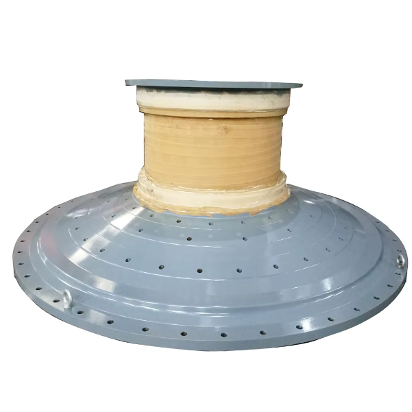
I. Functions and Structural Features of Discharge End Covers
The discharge end cover of a ball mill is a key component located at the discharge end of the cylinder. Its main functions include sealing the cylinder end, guiding ground materials to discharge, cooperating with sealing devices to prevent leakage of dust and media, and jointly bearing the radial load of the cylinder with the hollow shaft. Its performance directly affects the discharge efficiency and operational tightness of the ball mill.
Core Functions:
Material discharge guidance: Through internal conical structures or grid plates (in grid-type ball mills), qualified ground materials are directed to the discharge port to avoid retention;
Sealing protection: Cooperates with external sealing devices (such as labyrinth seals or pneumatic seals) to prevent leakage of dust and slurry (in wet ball mills) from the cylinder;
Structural load-bearing: As an end support for the cylinder, it is welded or bolted to the hollow shaft, bearing part of the cylinder's self-weight and impact loads from grinding media.
Structural Features:
Shape: Mostly a flanged disc-shaped structure, with the center connected to the hollow shaft and the edge fixed to the cylinder via flange bolts. Its diameter matches the cylinder (typically 1-5m);
Material: Requires both strength and toughness. Small and medium-sized mills commonly use Q235B carbon steel, while large or heavy-duty models adopt Q355B low-alloy steel (yield strength ≥355MPa) with a wall thickness of 25-80mm (increasing with diameter);
Design details: The inner side may be welded with grid plates (grid-type) or wear-resistant liners (material: ZGMn13). The center is machined with a stepped hole matching the hollow shaft, and the outer side is equipped with a sealing groove (for installing seals).
II. Manufacturing Process of Discharge End Covers (Taking Large Q355B End Covers as an Example)
1. Raw Material Pretreatment and Cutting
Raw material selection: Q355B steel plates with a thickness of 25-80mm are used, accompanied by material certificates (chemical composition: C ≤0.20%, Mn 1.2-1.6%). Mechanical properties must meet tensile strength of 470-630MPa and elongation ≥20%;
Cutting:
CNC flame or plasma cutting is used to cut according to the expanded size of the end cover (including flange allowance). The perpendicularity of the cutting surface is ≤1mm/m, with no cracks on the edge (checked with a 10x magnifying glass);
A machining allowance of 5-10mm is reserved for the central hollow shaft connection hole (φ200-φ500mm), and positions of flange bolt holes are pre-marked.
2. Forming and Rough Machining
Overall forming:
Small and medium-sized end covers are directly cut and formed; large end covers (diameter ≥3m) require pre-bending of the flange edge using a three-roll bending machine (curvature matching the cylinder). Local heating (200-250℃) is applied if necessary to prevent cold cracking;
Rough machining:
CNC vertical lathes rough-turn the flange surface and end face, leaving a 3-5mm finishing allowance with flatness ≤1mm;
The central stepped hole (matching the hollow shaft) is roughly bored, with a 2-3mm grinding allowance for the aperture and surface roughness Ra ≤12.5μm.
3. Welding and Heat Treatment (Key Processes)
Component welding:
If grid plates or liners need to be installed, ZGMn13 wear-resistant parts are welded to the inner side of the end cover using low-hydrogen electrodes (E5015-G) with a welding current of 280-350A. Preheating to 150℃ before welding and slow cooling after welding are required;
Butt welds between the flange and end cover body (large end covers may be welded in segments) use submerged arc automatic welding. Post-heating at 250-300℃ for 2 hours is performed immediately after welding to eliminate welding stress;
Overall quenching and tempering:
Large end covers undergo normalizing at 850-870℃ + tempering at 600-620℃, with hardness controlled at 180-230HBW to ensure machinability and toughness.
4. Finish Machining
Flange surface machining:
CNC vertical lathes finish-turn the flange joint surface to a flatness of ≤0.05mm/m and surface roughness Ra ≤3.2μm, ensuring the fitting gap with the cylinder flange is ≤0.1mm;
Flange bolt holes (16-48 holes, aperture φ25-φ60mm) are machined with a positional tolerance of ±0.1mm and cumulative hole distance error ≤0.2mm;
Central hole and sealing groove machining:
The central stepped hole is finish-bored, with the matching part of the hollow shaft controlled to tolerance H7 (e.g., a φ400mm hole allows +0.03-+0.08mm) and surface roughness Ra ≤1.6μm;
The outer sealing groove (width × depth: 15×8mm) is machined with a groove bottom roughness Ra ≤3.2μm and groove position deviation ±0.1mm.
5. Accessory Assembly and Surface Treatment
Wear-resistant liner installation: ZGMn13 liners are fixed to the inner side of the end cover via bolts with a pre-tightening torque ≥500N·m to ensure tight fitting without looseness;
Surface treatment:
Non-machined surfaces are sandblasted to Sa2.5 grade and coated with epoxy primer (thickness ≥60μm) + polyurethane topcoat (thickness ≥40μm);
Machined surfaces are coated with anti-rust oil (e.g., 30# machine oil), and waterproof sealing strips are attached to the sealing grooves.
III. Inspection Process of Discharge End Covers
1. Raw Material Inspection
Chemical composition analysis: A spectrometer detects C and Mn contents in Q355B steel plates to ensure compliance with standards (C ≤0.20%, Mn 1.2-1.6%);
Mechanical property verification: Tensile tests measure tensile strength (470-630MPa) and elongation (≥20%); impact tests (-20℃ impact energy ≥34J) are conducted.
2. In-Process Inspection (Key Nodes)
Inspection after cutting: Cutting size deviation ≤±3mm; no cracks or delamination at edges (sampling ultrasonic testing);
Welding quality inspection:
Appearance: Welds are free of pores and slag inclusions, with undercut depth ≤0.5mm and weld leg height meeting design requirements (≥10mm);
Non-destructive testing: 100% ultrasonic testing (UT) is performed on flange butt welds (compliant with JB/T 4730.3 Grade II); 100% penetrant testing (PT) is conducted on liner welding areas to ensure no surface cracks.
3. Dimensional Accuracy Inspection
Flange surface accuracy:
Flatness: Measured with a laser flatness meter, ≤0.05mm/m;
Flange thickness: Measured with a micrometer, deviation ±0.5mm;
Central hole and sealing groove:
Stepped hole diameter: Measured with an internal dial gauge, meeting H7 tolerance requirements;
Sealing groove: Width and depth measured with vernier calipers, deviation ±0.05mm; groove radial runout ≤0.03mm;
Bolt hole positions: Detected with a coordinate measuring machine, positional tolerance ±0.1mm, cumulative hole distance error ≤0.2mm.
4. Final Inspection of Finished Products
Assembly compatibility: Trial assembly with the cylinder flange and hollow shaft shows bolts can be freely inserted, and the fitting surface gap ≤0.1mm (checked with feeler gauges);
Sealing performance test: After installing seals, a 0.3MPa air pressure test (dry type) or water pressure test (wet type) is conducted, with no leakage within 30 minutes of pressure holding;
Appearance quality: Liner surfaces have no protrusions (≤1mm); machined surfaces are scratch-free; coating adhesion (cross-cut test ≥5B).
By strictly controlling welding quality and dimensional accuracy, the discharge end cover ensures stable cooperation with the cylinder and hollow shaft. With wear-resistant liners, its service life reaches 8-10 years, guaranteeing efficient discharge and sealed operation of the ball mill