This paper provides a detailed overview of ball mill liners, critical wear-resistant components mounted on the cylinder inner wall and end covers. These liners protect the cylinder and end covers from grinding media impact and material abrasion, enhance grinding efficiency via specific surface designs, and reduce material adhesion. They require high wear resistance, adequate toughness, and good fitting performance, with common materials including ZGMn13 high manganese steel (excellent toughness after water toughening), high chromium cast iron (superior wear resistance), and bimetallic composites (balancing toughness and wear resistance).
Detailed Introduction, Manufacturing Process, and Inspection Process of Ball Mill Liners
I. Functions and Structural Features of Ball Mill Liners
Ball mill liners are wear-resistant components installed on the inner wall of the cylinder and the inner side of end covers. They directly contact grinding media (steel balls, steel segments) and materials, serving as a "protective barrier" for efficient mill operation. Their core functions include: protecting the cylinder and end covers from impact and wear by grinding media, enhancing grinding efficiency through special surface shapes (e.g., increasing contact probability between media and materials), and reducing material adhesion and accumulation inside the cylinder. The performance and service life of liners directly affect the maintenance cost and production efficiency of ball mills.
Core Performance Requirements:
High wear resistance: Withstand high-frequency impact from steel balls (impact force up to thousands of N) and continuous abrasion from materials, requiring a service life of ≥8,000 hours;
Adequate toughness: Avoid brittle fracture due to steel ball impact (impact toughness ≥20J/cm²);
Good fit: Fit gap with the cylinder inner wall ≤1mm to prevent secondary wear caused by looseness during operation;
Ease of replacement: Moderate weight (≤50kg per piece, up to 100kg for large mills) for regular disassembly and replacement.
Structural and Material Features:
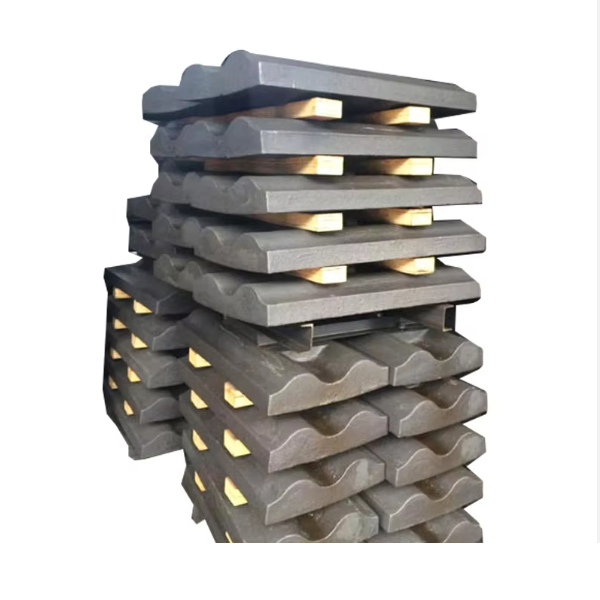
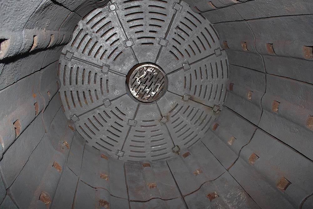
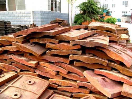
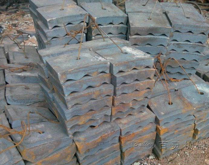
Structural types: Classified by shape as flat liners (for coarse grinding sections, with flat surfaces), corrugated liners (increase media lifting height, suitable for fine grinding sections), and stepped liners (reduce media sliding, commonly used in grid-type mills). Classified by installation position as cylinder liners and end cover liners (end cover liners are mostly fan-shaped to match end cover curvature).
Mainstream materials:
High manganese steel (ZGMn13): Most commonly used. After water toughening, it has excellent toughness (impact toughness ≥150J/cm²), and its surface hardens under impact (hardness up to 300-400HBW), suitable for hard rock and large steel ball working conditions;
High chromium cast iron (KmTBCr20Mo): 2-3 times more wear-resistant than high manganese steel (hardness ≥58HRC) but with lower toughness (impact toughness 10-20J/cm²), suitable for low-impact, fine grinding conditions (e.g., cement mills);
Bimetallic composite liners: Carbon steel base (ensuring toughness) with high chromium cast iron working surface (enhancing wear resistance), combining advantages of both materials, suitable for complex working conditions.
II. Manufacturing Process of Ball Mill Liners (Taking ZGMn13 High Manganese Steel Liners as an Example)
1. Raw Material Selection and Melting
Chemical composition control: Strictly proportion according to ZGMn13 standards (C 1.0-1.4%, Mn 11-14%, Si ≤0.8%, P ≤0.07%, S ≤0.05%), with Mn/C ratio ≥10 (to ensure water toughening effect);
Melting process:
Melt in an intermediate frequency induction furnace, heat to 1500-1550℃, and hold for 30 minutes to homogenize composition;
Deoxidation: Add ferrosilicon (0.5%) and aluminum ingots (0.1%) to remove oxygen and avoid gas hole defects;
Control tapping temperature at 1450-1480℃ to prevent grain coarsening.
2. Casting Forming (Key Process)
Mold design: Use resin sand molds (surface coated with zircon powder paint, thickness ≥1mm), with mold cavity size 3-5% larger than finished products (reserving shrinkage), and reasonable risers (feeding rate ≥15%);
Pouring process:
Pouring temperature 1380-1420℃, using bottom pouring (to avoid slag entrainment), with pouring time controlled at 30-60 seconds per piece;
For large liners (single weight ≥50kg), use a stepped pouring system to ensure stable filling of molten metal;
Shakeout and cleaning: Shake out after the casting cools to below 200℃, remove risers (using gas cutting, leaving 10mm from the body for subsequent grinding).
3. Water Toughening Treatment (Core Process for High Manganese Steel)
Heating: Slowly heat the casting to 1050-1100℃ (heating rate ≤100℃/h), hold for 2-4 hours (depending on thickness, 1 hour per 25mm), ensuring complete dissolution of carbides into austenite;
Water quenching: Quickly immerse the casting in water (water temperature ≤30℃) with a cooling rate ≥50℃/s until the core temperature drops below 200℃, inhibiting carbide precipitation;
Inspection: Hardness after water toughening ≤230HBW, metallographic structure is single austenite (no network carbides).
4. Machining
Rough machining: Mill the back of the liner (fitting surface with the cylinder) to flatness ≤1mm/m, leaving 1mm finishing allowance;
Finish machining:
Grind the fitting surface to roughness Ra ≤6.3μm, ensuring ≥80% contact area with the cylinder;
Drilling: Machine fixing bolt holes (aperture φ20-φ30mm) with position deviation ±0.5mm and hole perpendicularity ≤0.1mm/100mm;
Chamfering: Round all edges to R≥3mm to avoid stress concentration.
5. Surface Treatment and Marking
Cleaning: Sandblast the working surface (roughness Ra12.5μm) to remove oxide scale;
Marking: Stamp non-working surfaces with material (ZGMn13), batch number, weight, and production date;
Rust prevention: Coat non-working surfaces with anti-rust paint (thickness ≥40μm), and plug bolt holes with rubber stoppers.
III. Inspection Process of Ball Mill Liners
1. Raw Material and Melting Inspection
Pre-furnace chemical analysis: Spectral analysis to detect C and Mn contents (ensuring Mn/C ratio ≥10), with P and S contents ≤standard upper limits;
Melting records: Verify melting temperature and deoxidizer addition to ensure compliance with process requirements.
2. Casting Quality Inspection
Visual inspection: No cracks, shrinkage holes, or misruns, with cold shut depth ≤1mm;
Dimensional inspection: Measure length and width deviation (±2mm) and thickness deviation (±1mm) with a tape measure and template;
Non-destructive testing: 100% ultrasonic testing (UT) for large liners (qualified per JB/T 7260 Grade II), with no defects ≥φ3mm equivalent.
3. Water Toughening Quality Inspection
Hardness testing: Measure working surface with a Brinell hardness tester (HBW 180-230), with multi-point measurement deviation ≤20HBW on the same workpiece;
Metallographic analysis: Sample inspection of microstructure (austenitic matrix, no carbide precipitation) with grain size ≥5;
Impact test: Conduct room temperature impact test on samples (αk ≥150J/cm²), with fracture showing ductile fracture (fibrous).
4. Final Inspection of Finished Products
Fit test: Place the liner on a standard flat plate, check maximum gap with a feeler gauge ≤0.5mm;
Bolt hole inspection: Use gauges to check aperture tolerance (H12) and position to ensure bolts can be freely inserted;
Trial installation: Randomly select 3 liners for trial installation with the cylinder, checking tight fit and no looseness.
By strictly controlling water toughening quality and casting defects, ZGMn13 liners can achieve a service life of 8000-12000 hours under medium impact conditions, while high chromium cast iron liners can reach over 15000 hours in low-impact fine grinding environments. Selection should be based on material hardness and grinding media size