A ball mill coupling is a core transmission component connecting the motor, reducer, and ball mill cylinder (or main shaft). Its primary functions are to transmit torque, compensate for installation errors (e.g., axial, radial, and angular displacements), and buffer impact loads, ensuring stable operation of the ball mill under heavy-load and low-speed conditions.
Ball mills operate in environments often accompanied by vibration, dust, and high temperatures, so couplings must meet the following requirements:
High strength: Capable of withstanding torque ranging from thousands to tens of thousands of N·m;
Wear and corrosion resistance: Adaptable to dusty and humid environments;
Buffering performance: Reducing rigid impacts between the motor and cylinder;
Easy maintenance: Convenient for installation, disassembly, and replacement of vulnerable parts.
Depending on the specifications (e.g., small laboratory ball mills, large mineral processing ball mills) and working conditions, common types include:
Elastic Pin Coupling
Structure: Composed of two half-couplings, elastic pins (rubber or nylon), and baffles.
Characteristics: Simple structure, low cost, capable of compensating for minor radial and angular displacements, with moderate buffering performance. Suitable for small and medium-sized ball mills.
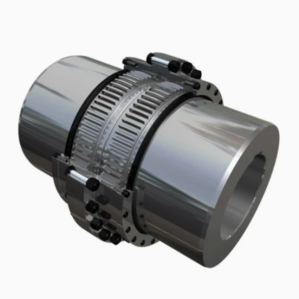
Gear Coupling
Structure: Consists of two half-couplings with external teeth and an outer sleeve with internal teeth. The tooth profile is usually involute, and grease lubrication is typically used.
Characteristics: High load-bearing capacity (torque up to 10⁶ N·m or more), capable of compensating for large radial, axial, and angular displacements. Suitable for large ball mills but requires high installation accuracy and regular lubrication.
Diaphragm Coupling
Structure: Connects two half-couplings via metal diaphragms (e.g., stainless steel) with bolts. Displacements are compensated through elastic deformation of the diaphragms.
Characteristics: No clearance, no need for lubrication, resistant to high and low temperatures. Suitable for occasions requiring high transmission accuracy (e.g., ceramic ball mills), but with higher cost and slightly lower load-bearing capacity than gear couplings.
Universal Coupling
Structure: Composed of two fork-shaped joints, a cross shaft, and bearings, capable of transmitting torque at large angles (≤35°).
Characteristics: Suitable for working conditions with large axis offsets, often used in auxiliary transmission systems of ball mills (e.g., feed inlet adjustment mechanisms).
Taking the gear coupling (the most widely used coupling in large ball mills) as an example, its manufacturing process is as follows:
Materials: Half-couplings and outer sleeves are typically made of high-strength alloy structural steel (e.g., 42CrMo, 35CrNiMo), requiring tensile strength ≥800MPa and impact toughness ≥60J/cm². Gear tooth surfaces can use 20CrMnTi (carburized and quenched) to improve wear resistance.
Pretreatment:
Raw material inspection: Spectral analysis (to ensure qualified composition) and flaw detection (ultrasonic testing for internal cracks);
Forging: Heating the steel billet (1100-1200℃) and forging (open die forging or die forging) to eliminate internal porosity and refine grains;
Annealing/normalizing: Annealing after forging (650-700℃ for 4-6h, slow cooling) to reduce hardness (≤250HBW) for subsequent processing.
Rough machining:
Turning: Turning the outer circle, inner hole, and end face on a lathe, leaving a machining allowance of 2-5mm;
Drilling: Drilling bolt holes (for connecting diaphragms or gears) with a 1-2mm allowance.
Heat treatment:
Quenching and tempering: 42CrMo and similar materials undergo quenching (850-880℃ oil quenching) + high-temperature tempering (550-600℃) to achieve a hardness of 280-320HBW, ensuring matrix strength;
Tooth surface strengthening (for gear couplings): 20CrMnTi external teeth undergo carburizing (900-930℃, carburized layer depth 1.5-3mm) + quenching (850℃ oil quenching) + low-temperature tempering (180-200℃), resulting in a tooth surface hardness of 58-62HRC and core hardness of 25-35HRC.
Turning: Precision turning of the journal, end face, and matching hole of the half-coupling to ensure dimensional accuracy (e.g., journal tolerance IT7-IT8, surface roughness Ra≤1.6μm);
Tooth profile machining:
Hobbing: Rough machining of the tooth profile to ensure pitch accuracy (GB 10095 Grade 7);
Shaving/honing: Finish machining of the tooth surface to reduce surface roughness (Ra≤0.8μm);
For carburized materials such as 20CrMnTi, gear grinding is required after carburizing to correct heat treatment deformation, ensuring tooth profile accuracy (GB 10095 Grade 6);
Drilling and tapping: Machining connecting bolt holes (e.g., M20-M48) with thread accuracy reaching 6H.
Non-tooth surfaces: After sandblasting for rust removal, apply primer (e.g., epoxy zinc-rich paint) and topcoat (e.g., polyurethane paint) with a total thickness ≥80μm to improve corrosion resistance;
Inner tooth sleeves of gear couplings: Apply anti-rust grease (e.g., lithium-based grease) to the inner tooth surface and install seals (e.g., O-rings) to prevent grease leakage.
For gear couplings: Connect the two external tooth half-couplings to the motor shaft and reducer shaft (or cylinder main shaft) via key connections (flat keys or splines), ensuring a fitting clearance of H7/k6;
Fit the internal tooth outer sleeve, check the tooth backlash (0.1-0.3mm), and install grease nipples;
For elastic couplings: Install elastic pins with a transition fit (H7/m6) between pins and holes to prevent loosening.
Inspection covers raw materials, processing, and finished products to comply with design standards (e.g., GB/T 4323 Elastic Sleeve Pin Couplings, GB/T 5014 Elastic Pin Couplings, JB/T 8854.3 Gear Couplings).
Chemical composition analysis: Use a direct-reading spectrometer to detect elements such as C, Si, Mn, Cr, and Mo, meeting material standards (e.g., 42CrMo requires C: 0.38-0.45%, Cr: 0.90-1.20%);
Mechanical property testing: Tensile testing (for tensile strength and yield strength), impact testing (-20℃ impact energy ≥40J), and hardness testing (≤250HBW after annealing);
Flaw detection: Ultrasonic testing of forgings (GB/T 6402) to ensure no internal defects ≥φ3mm; magnetic particle testing (GB/T 15822) to check for surface cracks.
Dimensional accuracy inspection:
Journal and inner hole diameter: Measured with a micrometer or internal dial gauge, with tolerances meeting IT7-IT8;
End face perpendicularity: Measured with a dial gauge on a rotary table, with an error ≤0.02mm/100mm;
Tooth profile inspection:
Use a gear runout tester to measure radial runout of the gear ring (≤0.05mm) and end face runout (≤0.04mm);
Use a gear measuring center to detect cumulative pitch error (≤0.1mm/100mm) and tooth profile error (≤0.015mm);
Surface roughness: Measured with a profilometer, with non-mating surfaces Ra≤12.5μm, mating surfaces Ra≤3.2μm, and tooth surfaces Ra≤0.8μm.
Hardness testing: Use a Rockwell hardness tester to measure tooth surface hardness (carburized layer of gear couplings ≥58HRC, core 25-35HRC);
Carburized layer depth: Observed with a metallographic microscope to ensure effective case depth (1.5-3mm);
Metallographic structure: Check martensite grade of the tooth surface (≤Grade 3), with no network carbides allowed.
Assembly dimension inspection:
Total length of the coupling: Measured with a steel tape, with an error ≤±1mm;
Coaxiality of the two shafts: After assembly, use a dial gauge to detect radial circular runout (≤0.1mm/m) and axial movement (≤0.2mm);
Dynamic balance testing: For couplings with a speed ≥1000r/min, conduct dynamic balance tests (GB/T 9239) with an unbalance ≤50g·mm/kg;
Load-bearing testing: For large gear couplings, conduct static torque tests (loading to 1.5 times the rated torque, holding for 10min with no plastic deformation);
Sealing performance: For gear couplings, conduct pressure tests (0.2MPa) after grease injection, with no leakage within 30min.
Each batch of products must be accompanied by an inspection report, including:
Raw material certification and flaw detection reports;
Records of key dimension measurements and tooth profile inspection reports;
Reports on heat treatment hardness and carburized layer depth;
Results of finished product dynamic balance and static torque tests.
Strict manufacturing processes and inspection procedures ensure the reliability and service life of ball mill couplings, meeting the requirements of long-term heavy-load operation of ball mills.