This article elaborates on the ball mill shaft, a core component that transmits torque, bears heavy loads (up to thousands of tons), and connects the cylinder and transmission system, with 45# steel and 42CrMo alloy steel as common materials for different sizes. It details the manufacturing process of 42CrMo shafts, including raw material pretreatment, forging, heat treatment (normalizing and quenching-tempering), rough machining, semi-finishing, precision grinding, and assembly. Additionally, it outlines comprehensive inspection procedures covering raw materials (chemical composition, mechanical properties), heat treatment (hardness, metallographic structure), machining accuracy (dimensional and geometric tolerances), and final product tests (surface quality, dynamic balance, hydrostatic test). These ensure the shaft meets strength, toughness, and precision requirements, supporting stable and efficient operation of ball mills.
Detailed Introduction, Manufacturing Process and Inspection Process of Ball Mill Shaft
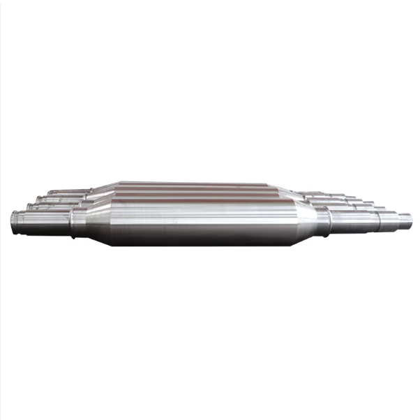
I. Functions and Structural Characteristics of Ball Mill Shaft
The ball mill shaft (also known as "hollow shaft") is a core component connecting the cylinder and the transmission system. Its main functions are transmitting torque, supporting the total weight of the cylinder and internal materials, and transferring loads to the foundation through the bearing seat. Its performance directly determines the operational stability and service life of the ball mill, serving as the "backbone" of the equipment.
Core Functions:
Torque transmission: Transmit the torque output by the motor through the reducer to the cylinder, driving the cylinder to rotate (rotational speed: 15-30 rpm);
Load bearing: Bear the total weight of the cylinder, grinding media (steel balls) and materials (up to thousands of tons for large ball mills);
Sealing connection: Cooperate with the sealing device at the feed and discharge ports to prevent material leakage.
Structural Characteristics:
Shape: A stepped hollow cylinder (hollow structure reduces weight), with journal (matching bearings) at both ends and flange bolt connection with the cylinder in the middle;
Dimensions: Shaft diameter of small and medium-sized ball mills is usually 300-800 mm, while that of large ones can exceed 1500 mm; length matches the cylinder (2-10 m);
Material: Requires both high strength and toughness. Small and medium-sized shafts use 45# high-quality carbon steel (low cost, good machinability), while large or heavy-duty models adopt 42CrMo alloy structural steel (tensile strength ≥ 800 MPa, impact toughness ≥ 60 J/cm²).
II. Manufacturing Process of Ball Mill Shaft (Taking 42CrMo Material as an Example)
The manufacturing of ball mill shafts involves forging, heat treatment, precision machining and other processes. The core procedures are as follows:
1. Raw Material Pretreatment and Forging
Raw material selection: Use 42CrMo round steel with diameter 300-1800 mm, accompanied by material certification (chemical composition: C 0.38-0.45%, Cr 0.9-1.2%, Mo 0.15-0.25%);
Forging process:
Heating: Heat the round steel in a natural gas furnace to 1100-1150℃ (austenitizing temperature) and hold for 2-4 hours (adjusted according to diameter);
Forging: Adopt free forging or hydraulic press die forging, with staged upsetting and drawing to ensure the forging ratio (length-diameter ratio) ≤ 3.5 and eliminate internal porosity;
Post-forging treatment: Cool slowly to 600℃ and then air-cool to avoid cracks caused by excessive temperature difference; control forging allowance at 15-20 mm.
2. Heat Treatment (Key Process Determining Mechanical Properties)
Normalizing: Heat to 860-880℃, hold for 3 hours, then air-cool to refine grains, eliminate forging stress, and reduce hardness to 220-250 HBW;
Quenching and tempering:
Quenching: Heat to 840-860℃, hold, then oil-cool (cooling rate ≥ 50℃/s) to ensure core hardening;
High-temperature tempering: Hold at 580-620℃ for 4 hours, then air-cool to achieve final hardness of 280-320 HBW, balancing strength and toughness;
Flaw detection: Conduct 100% ultrasonic testing (UT) after quenching and tempering (compliant with JB/T 4730.3 Level I), with no cracks or flakes allowed.
3. Rough Machining and Semi-Finishing
Rough machining:
Turning: Turn the outer circle and end face on a floor lathe or CNC lathe, leaving 8-10 mm machining allowance;
Drilling and boring: Bore the hollow inner hole (diameter 1/3-1/2 of the shaft diameter) to remove internal stress concentration areas;
Semi-finishing:
Finish turning: Further turn the journal and flange end face, leaving 2-3 mm grinding allowance, and machine a process table at the journal (for subsequent positioning);
Journal grinding: Grind the journal matching the bearing on a universal cylindrical grinder (tolerance IT6, surface roughness Ra ≤ 0.8 μm), ensuring cylindricity ≤ 0.005 mm/m;
End face grinding: Grind the flange end face (flatness ≤ 0.02 mm/m) to ensure perpendicularity to the axis ≤ 0.01 mm/100 mm;
Precision inspection: Use a coordinate measuring machine to check key dimensions (e.g., journal diameter, flange thickness) with deviation controlled within ±0.02 mm;
Surface treatment: Phosphating treatment on the journal surface (for rust prevention), and primer + topcoat on non-mating surfaces (total thickness ≥ 80 μm).
5. Final Inspection and Trial Assembly
Cleaning: Clean surface oil and iron filings with diesel;
Trial assembly: Preassemble with the bearing seat and cylinder flange, check the fit between the journal and bearing inner ring (interference 0.01-0.03 mm), and the position degree of flange connection holes (≤ 0.1 mm).
III. Inspection Process of Ball Mill Shaft
Inspection runs through the entire manufacturing process to ensure compliance with GB/T 3077 Alloy Structural Steels and industry standards. Key links are as follows:
1. Raw Material and Forging Inspection
Chemical composition analysis: Use a direct-reading spectrometer to detect 42CrMo composition, ensuring Cr and Mo contents are within standard ranges;
Forging quality inspection:
Macrostructure: Etch test (10% nitric acid alcohol solution), with no shrinkage, scab, or cracks allowed;
Mechanical properties: Take forging samples for tensile test (tensile strength ≥ 800 MPa, yield strength ≥ 600 MPa) and impact test (-20℃ impact energy ≥ 40 J).
2. Heat Treatment Inspection
Hardness testing: Measure hardness at multiple points on the journal and flange with a Brinell hardness tester, ensuring hardness of 280-320 HBW (uniformity deviation ≤ 20 HBW);
Metallographic structure: Inspect the quenched and tempered structure (tempered sorbite, grade ≤ 3) with no network carbides or free ferrite.
3. Machining Accuracy Inspection
Dimensional accuracy:
Journal diameter: Measured with a micrometer (tolerance IT6, e.g., φ500 mm journal allows +0.03-+0.05 mm);
Inner hole diameter: Measured with an internal dial gauge, tolerance H8 (ensuring fit clearance with the feed pipe);
Geometric tolerance:
Radial runout: Measured on a precision lathe or deflection instrument, ≤ 0.02 mm/m at the journal;
Straightness: Detected with a level, full-length deviation ≤ 0.05 mm/m.
4. Final Product Inspection
Surface quality: Visually or by penetrant testing (PT) to check the surface, with no scratches or bumps (depth ≤ 0.5 mm);
Dynamic balance test: For shafts with rotational speed ≥ 30 rpm, conduct dynamic balance testing (unbalance ≤ 50 g·mm/kg);
Hydrostatic test: Perform a 0.5 MPa hydrostatic test on the hollow shaft inner hole, with no leakage for 30 minutes (to ensure sealing performance).
IV. Summary
The manufacturing of ball mill shafts requires strict control of forging quality, heat treatment processes, and machining accuracy. Full-process inspection ensures their load-bearing capacity and operational stability. Reasonable material selection (e.g., 42CrMo) and optimized quenching-tempering parameters can extend the shaft's service life to over 5 years, providing core support for efficient operation of the ball mill.