This article details ball mill bearing blocks, which bear radial/axial loads, ensure shaft stability, and feature materials like HT300, QT450-10, or Q355B. It covers manufacturing processes for cast (molding, pouring, aging, machining) and welded (blanking, welding, machining) types, plus full-process inspections (raw materials, blanks, in-process, final products) to guarantee dimensional accuracy, strength, and reliability, meeting heavy-load, continuous operation needs.
Detailed Introduction to Ball Mill Bearing Blocks and Their Manufacturing & Inspection Processes
I. Overview and Structural Features of Ball Mill Bearing Blocks
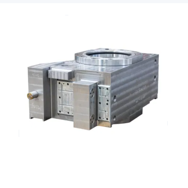
The ball mill bearing block is a core component supporting the rotation of the mill cylinder. Its primary function is to fix the bearing, withstand radial and axial loads from the cylinder and internal materials, and ensure stable rotation of the shaft system (hollow shaft). Its performance directly affects the operating accuracy, stability, and service life of the ball mill.
Core Functions:
Load-bearing: Sustains the total weight of the cylinder, grinding media, and materials (up to tens or hundreds of tons) and absorbs impact loads during rotation;
Positioning: Ensures coaxiality and rotational accuracy of the hollow shaft through cooperation with the bearing;
Sealing and lubrication: Integrates lubrication channels and sealing structures to provide lubrication for bearings and prevent ingress of dust and coolant.
Structural Features:
Material: Small and medium-sized ball mills typically use gray cast iron (HT300) (excellent castability and shock absorption); large or heavy-duty mills adopt ductile iron (QT450-10) or welded structural steel (Q355B) (higher strength).
Structural types: Integral (small to medium-sized) and split (large-sized, for easy installation and maintenance). They usually include bearing mounting holes (interference fit with bearing outer rings), locating spigots, bolt holes, lubrication holes, and cooling fins.
II. Manufacturing Process of Ball Mill Bearing Blocks
Based on materials, the manufacturing processes are divided into casting (for cast iron bearing blocks) and welding (for steel bearing blocks), with core procedures as follows:
(A) Cast Bearing Blocks (HT300 as an example)
Mold Design and Core Making
Sand molds (wooden or resin) are fabricated based on 3D models, with a machining allowance of 3-5mm. Risers are designed to avoid shrinkage cavities;
Critical areas (e.g., bearing holes) use cold-box core making to ensure dimensional accuracy.
Melting and Pouring
Molten iron composition control: C 3.2-3.6%, Si 1.8-2.2%, Mn 0.8-1.2%, S≤0.12%, P≤0.15%;
Pouring at 1380-1450℃ using step pouring to reduce stress concentration and ensure casting density.
Aging Treatment
Castings undergo natural aging for 2-4 weeks (or artificial aging: 200-250℃ for 8h) to eliminate casting stress and prevent subsequent machining deformation.
Rough Machining
CNC lathes or boring machines process bearing holes (leaving 2-3mm finishing allowance), end faces, and locating spigots, ensuring flatness of datum surfaces ≤0.1mm/100mm.
Semi-Finishing and Secondary Aging
Finish turning outer circles and end faces, leaving 1-1.5mm grinding allowance;
Secondary aging (180-220℃ for 4h) to further stabilize dimensions.
Surface grinders machine locating spigot end faces: flatness ≤0.03mm/100mm, perpendicularity to bearing hole axis ≤0.02mm/100mm;
Drilling and tapping lubrication holes and connecting holes: thread accuracy 6H, hole position tolerance ±0.1mm.
(B) Welded Bearing Blocks (Q355B as an example)
Blanking and Forming
CNC cutting for blanking (plate thickness ≥20mm). Bearing hole areas are spliced with forged steel flanges (20# steel) to enhance load-bearing strength.
Welding Process
Welding method: Submerged arc welding or gas metal arc welding, with V-shaped weld grooves (60° angle);
Welding sequence: First weld low-stress areas, then main welds, using layered welding (each layer ≤5mm thickness). Post-weld hammering to relieve stress;
Post-weld treatment: Stress relief annealing at 300℃ for 6h to eliminate welding stress (preventing cracking).
Machining
Follows the same rough machining, secondary aging, and finish machining steps as cast bearing blocks, but welded surfaces must first be milled flat (surface roughness Ra≤12.5μm).
III. Inspection Process of Ball Mill Bearing Blocks
Inspection covers the entire production process to ensure dimensional accuracy, mechanical properties, and operational reliability:
(A) Raw Material and Blank Inspection
Material inspection:
Cast iron parts: Spectral analysis to verify chemical composition (e.g., C and Si content in HT300) and tensile testing to check tensile strength ≥300MPa;
Welded parts: Verify steel plate certificates; forged flanges undergo UT inspection (compliant with JB/T 5000.15 Class II).
Blank defect inspection:
Cast parts: MT inspection (no surface cracks or shrinkage), with focus on bearing holes (no pores ≥φ3mm);
Welded parts: 100% UT inspection for welds (no incomplete fusion or slag inclusions) and MT inspection (no surface cracks).
(B) In-Process Inspection (Key Nodes)
After rough machining:
Check bearing hole diameter (uniform allowance) and spigot diameter (tolerance ±0.5mm) using vernier calipers or CMM.
After heat treatment:
Hardness testing: Brinell hardness tester for cast iron (180-240HBW) and annealed welded parts (≤220HBW).
Bolt hole position: Gauge verifies coaxiality of connecting holes with locating spigot (≤0.1mm).
Pressure and sealing inspection:
Lubrication hole pressure test: 0.5MPa compressed air for 30s, with soap solution checking for no leakage;
Overall sealing: Simulated bearing assembly, oil filling (to 1/2 of bearing hole), 10min rotation, and inspection for no leakage.
Appearance inspection:
Surface painting (primer + topcoat, total thickness 60-80μm) with no runs or peeling; clear markings (model, material).
IV. Summary
Manufacturing of ball mill bearing blocks requires balancing strength and precision. Casting processes prioritize shock absorption, while welding processes focus on heavy-load capacity. Strict inspection (especially for dimensional accuracy and defect control) is critical to ensuring load-bearing capacity and service life. In practice, process parameters are adjusted based on mill specifications (e.g., wall thickness of bearing holes ≥50mm for mills ≥φ3m) to meet heavy-duty, continuous operation requirements