The ball mill gearbox is a core component of the ball mill's transmission system, whose primary function is to convert the high speed of the motor into the low speed required by the ball mill cylinder (typically 15-30 rpm) while amplifying torque, ensuring stable rotation of the cylinder for material grinding. Given that ball mills operate in heavy-load, dusty, and continuous-run environments (often 24/7), their gearboxes must meet the following requirements:
High load-bearing capacity: Capable of withstanding the total weight of the cylinder, grinding media, and materials (ranging from tens to hundreds of tons) and resisting impact loads (e.g., transient overloads due to uneven feeding).
High transmission efficiency: Generally requiring ≥90% efficiency to minimize energy loss.
High reliability: Designed for long-term continuous operation, with vulnerable parts (e.g., gears, bearings) having a service life matching the ball mill (typically ≥10,000 hours without major overhauls).
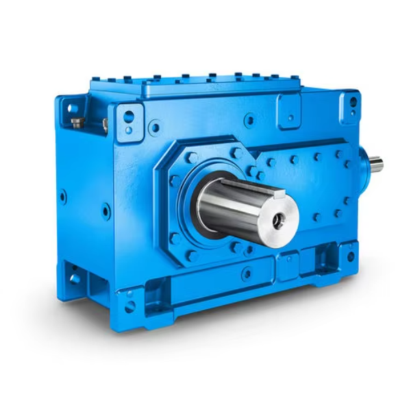
Typical structural components:
Housing (cast or welded, supporting internal parts);
Gear train (including input shaft gear, intermediate shaft gear, output shaft gear, mostly hard-faced cylindrical or bevel gears, with stages determined by the transmission ratio);
Shafting (input shaft, intermediate shaft, output shaft, usually made of 40Cr or 42CrMo);
Bearings (mostly spherical roller bearings or tapered roller bearings, bearing radial and axial loads);
Seals (framework oil seals, O-rings, etc., preventing lubricant leakage and dust ingress);
Lubrication system (oil sump lubrication or forced lubrication; large gearboxes may include oil pumps and coolers).
The manufacturing process, tailored to structural complexity, material requirements, and performance indicators, includes four core stages: housing manufacturing, gear processing, shafting processing, and assembly.
The housing, the "framework" of the gearbox, requires high rigidity and dimensional accuracy. Common materials are gray cast iron (HT300) (for small to medium gearboxes) or welded structural steel (Q355B) (for large gearboxes, weight ≥5 tons).
Gears, core transmission components, require high-precision tooth profiles and wear resistance:
Blank preparation:
Forging: Die forging (forging allowance 5-8mm), followed by normalizing (860-880℃ for 2h, air cooling) to eliminate forging stress, with hardness controlled at 180-220HBW.
Inspection: UT for internal defects (no cracks, shrinkage cavities), MT for surface defects.
Rough machining:
Turning: CNC lathe machining of outer diameter, end faces, and inner holes (leaving 2-3mm finishing allowance), ensuring datum perpendicularity ≤0.02mm/100mm.
Tooth blank processing:
Hobbing: Gear hobbing to machine tooth profiles (leaving 0.3-0.5mm grinding allowance), with cumulative pitch error ≤0.1mm and helix error ≤0.05mm/100mm.
Chamfering: Removing tooth end burrs to prevent cracking during heat treatment.
Heat treatment:
Carburizing and quenching: Carburizing at 920-940℃ (case depth 1.2-2.0mm, adjusted by module), quenching at 850℃ (oil cooling), and low-temperature tempering at 200-220℃. Surface hardness 58-62HRC, core hardness 30-45HRC.
Straightening: Pressure straightening for deformation exceeding tolerance (radial runout >0.1mm), avoiding impact.
Finish machining:
Internal/external grinding: Grinding inner holes or outer circles using tooth surfaces as datums (or dedicated mandrels), with roundness ≤0.005mm and cylindricity ≤0.01mm/100mm.
Gear grinding: CNC form grinding or worm grinding to achieve tooth profile accuracy GB/T 10095.1-2008 Grade 6, helix accuracy Grade 6, and surface roughness Ra≤0.8μm.
Honing (optional): For high-speed gears, honing to reduce surface roughness to Ra≤0.4μm and minimize meshing noise.
Shafts bear torque and radial loads from gears:
Blank preparation:
Forging: Open die forging or die forging (for length-diameter ratio >5), followed by normalizing (850-870℃ for 2h, air cooling) to control hardness at 180-220HBW.
Inspection: UT for internal defects, MT for surface defects.
Rough machining:
Quenching and tempering:
Semi-finish machining:
Turning: Finish turning steps (leaving 0.5-1mm grinding allowance) and threading (leaving 0.1-0.2mm grinding allowance).
Milling: CNC milling of keyways (symmetry ≤0.05mm, depth tolerance ±0.05mm).
Finish machining:
Grinding: Cylindrical grinding of bearing and gear mating surfaces (roundness ≤0.003mm, cylindricity ≤0.005mm/100mm, surface roughness Ra≤0.8μm);
Thread grinding (for high-precision threads): Ensuring thread accuracy 6g and surface roughness Ra≤1.6μm.
Assembly ensures positional accuracy and transmission stability:
Part cleaning and pretreatment:
All parts are cleaned with kerosene (removing oil and debris); bearings and seals are cleaned with dedicated agents, dried, and coated with anti-rust oil;
Checking part fits (e.g., interference fit H7/k6 for bearings and shafts, clearance fit H7/g6).
Shafting assembly:
Press-fitting bearings: Heating bearings to 80-100℃ for press-fitting onto journals, avoiding hammering;
Gear-shaft assembly: Interference fits use hot fitting (gears heated to 120-150℃) or cold fitting (shafts cooled with liquid nitrogen). Post-assembly coaxiality check (radial runout ≤0.02mm).
In-housing assembly:
Installing shafting components: Mounting input, intermediate, and output shaft assemblies into the lower housing. Adjusting bearing seat positions with dial indicators to ensure shaft parallelism (≤0.03mm/1000mm);
Gear meshing adjustment: Checking backlash (0.15-0.3mm for Grade 6 gears) with feeler gauges or lead pressing, and contact patterns (≥60% along tooth height, ≥70% along tooth length) with marking paste. Optimizing meshing by adjusting shim thickness.
Housing closing and fastening:
Applying sealant (e.g., Loctite 510) to the lower housing joint surface, then closing the upper housing. Tightening bolts uniformly (diagonal sequence, 2-3 stages) to specified torque (e.g., 350-400N·m for M20 bolts);
Checking housing fit (0.05mm feeler gauge should not penetrate).
Accessory installation:
Installing seals (framework oil seal lips facing inward, 0.1-0.2mm interference with shafts);
Installing lubrication systems (oil level gauges, breathers, drain plugs). Large gearboxes add oil pumps, filters, and coolers.
No-load test run:
Filling with gear oil (e.g., L-CKD 220 extreme pressure industrial gear oil) to the oil level gauge midline. Running no-load for 2h at 1.2× operating speed;
Monitoring: No abnormal noise (≤85dB), bearing temperature rise ≤40℃ (ambient +40℃), no leakage.
Inspection covers raw material inspection, in-process inspection, and final product inspection:
Material certification: Verifying mill certificates (chemical composition, mechanical properties), e.g., 20CrMnTi requiring Cr 1.0-1.3%, Mn 0.8-1.1%;
Physical and chemical testing: Sampling for chemical analysis (direct-reading spectrometer) and mechanical property tests (tensile and impact testing machines);
Inspection: 100% UT for forgings (JB/T 5000.15-2007 Class II) and MT for critical casting surfaces (no cracks or pores).
Housing inspection:
Cast housings: Dimensional checks (CMM, critical hole positional tolerance ≤0.05mm), surface quality (no sand holes or shrinkage), and pressure testing (0.3MPa for 30min, no leakage);
Welded housings: UT/MT for welds (JB/T 5000.3-2007 Class II) and post-weld deformation (flatness ≤0.05mm/100mm).
Gear inspection:
Post-heat treatment: Surface hardness (58-62HRC, Rockwell tester), case depth (1.2-2.0mm, metallographic method), core hardness (30-45HRC);
Post-finishing: Tooth profile accuracy (gear measuring center, Grade 6), helix accuracy (Grade 6), cumulative pitch error (≤0.05mm), and surface roughness (Ra≤0.8μm, profilometer).
Shaft inspection:
Post-heat treatment: Hardness (280-320HBW, Brinell tester) and quenched-tempered layer uniformity;
Post-finishing: Journal roundness (≤0.003mm, roundness meter), cylindricity (≤0.005mm/100mm), and keyway symmetry (≤0.03mm, dial indicator + V-block).
Appearance and dimensions:
Paint quality (no runs or peeling, thickness 60-80μm, coating thickness gauge) and clear markings (model, ratio, weight);
Mounting dimensions (input/output shaft center height, flange spigot diameter, CMM-tested, tolerance ±0.1mm).
Performance testing:
Efficiency: Calculated via torque sensors (≥90%);
Vibration: Vibration velocity ≤1.1mm/s (GB/T 6404.2-2005, vibration meter);
No-load test: Running for 2h, monitoring bearing temperature (≤80℃, infrared thermometer), noise (≤85dB, sound level meter), and leakage;
Load test: Step loading at 25%, 50%, 75%, 100% rated power (1h per step), with 100% load running for 4h;
Overload test: 125% rated load for 1min, checking for plastic deformation in gears and bearings.
Pre-packaging final inspection:
Cleaning oil residues, filling with anti-rust oil, verifying accessories (manuals, certificates, spare parts lists), and ensuring weatherproof/shockproof packaging.