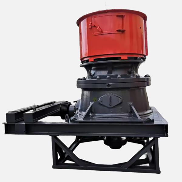
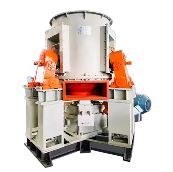
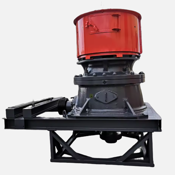
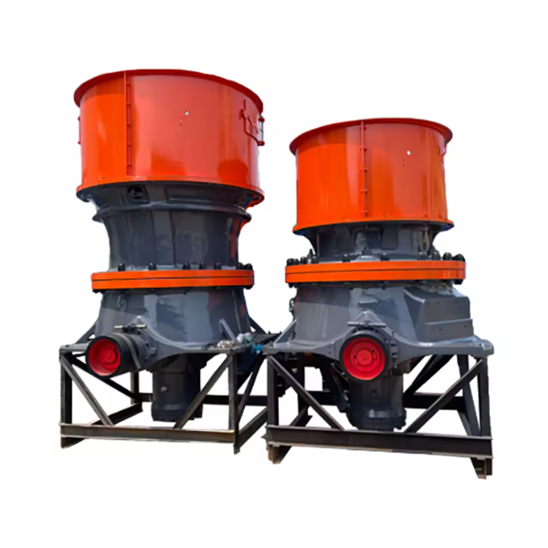
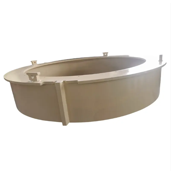
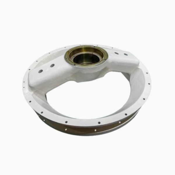
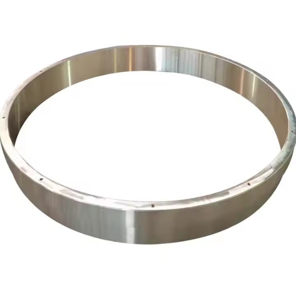
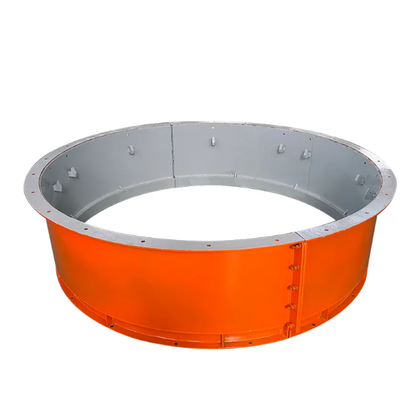
This paper elaborates on the cone crusher upper frame, a foundational structural component located in the upper section of the crusher, which supports key assemblies like the fixed cone, adjustment ring, and feed hopper. Its main functions include structural support (bearing loads up to hundreds of tons and transferring them), forming the crushing chamber (cooperating with the moving cone), ensuring component alignment, and protecting internal parts. The upper frame, a large hollow cylindrical or conical casting, consists of components such as the frame body (made of high-strength cast steel ZG310–570 or ductile iron QT600–3), fixed cone mounting surface, adjustment ring guide, flange connections (top and bottom flanges), reinforcing ribs, lubrication and inspection ports, and optional cooling jacket, each with specific structural features. The casting process of the upper frame involves material selection, pattern making (with shrinkage allowances and draft angles), molding (using green sand or resin-bonded sand molds), melting and pouring (with controlled temperatures and flow rates), cooling and shakeout, and heat treatment (normalization and tempering for cast steel, annealing for ductile iron). Its machining and manufacturing process includes rough machining, intermediate heat treatment, finish machining (of flanges, internal taper, and adjustment ring guide), and surface treatment. Quality control processes cover casting quality inspection (ultrasonic and magnetic particle testing), dimensional accuracy checks (using CMM and laser tracker), material testing (chemical composition and hardness testing), load testing, and assembly fit verification. These processes ensure the upper frame has sufficient structural integrity and dimensional precision to guarantee stable operation of the cone crusher in heavy-duty applications
This paper details the cone crusher torch ring, a vital sealing and protective component situated between key assemblies like the adjustment ring and main frame, or moving cone and fixed cone. Its primary functions include high-temperature sealing (withstanding up to 150°C), preventing contamination, thermal insulation, and vibration absorption, requiring heat resistance, oil resistance, and mechanical strength. The torch ring has a composite structure, consisting of a metal framework (low-carbon or alloy cast steel) with a U/L-shaped cross-section, a sealing liner (high-temperature rubber, graphite composite, or metal-reinforced felt), retention grooves, flange edges, and optional vent holes. The metal framework is produced via sand casting: material selection (Q235 or ZG230–450), pattern making with shrinkage allowances, green sand molding, melting and pouring (1450–1480°C), cooling and shakeout, and annealing for stress relief. The machining and manufacturing process involves framework machining, sealing liner preparation, liner bonding with heat-resistant adhesive, finishing, and optional surface treatment. Quality control includes material testing (chemical composition, tensile strength, hardness), dimensional checks (CMM for accuracy), bond strength testing, seal performance evaluations (pressure and heat cycling), and visual/functional inspections. These ensure the torch ring provides reliable sealing in high-temperature, high-vibration conditions, safeguarding internal components and ensuring efficient crusher operation.
This paper elaborates on the Cone Crusher Hopper component, a crucial material guiding part located at the top of the crusher. Its main functions include material collection and storage, uniform distribution, impact buffering, and contamination prevention, requiring high wear resistance, structural strength, and corrosion resistance. The hopper is typically funnel-shaped or rectangular, composed of the hopper body, feed grate/screen, wear liners, reinforcing ribs, mounting flange, access door, and optional vibration device mounts, each with specific structural features and roles. For cast steel variants, the casting process involves material selection (high-strength cast steel like ZG270–500), pattern making, molding, melting and pouring, cooling and shakeout, heat treatment, and casting inspection. Most hoppers, however, are fabricated from steel plates through plate cutting, forming and bending, welding assembly, post-weld treatment, machining of mounting features, liner installation, and surface treatment. Quality control processes cover material validation, dimensional accuracy checks, weld quality inspection, structural integrity testing, liner performance testing, and final inspection. These ensure the hopper can withstand abrasive wear and impact, guaranteeing continuous and efficient operation of the cone crusher in relevant applications.
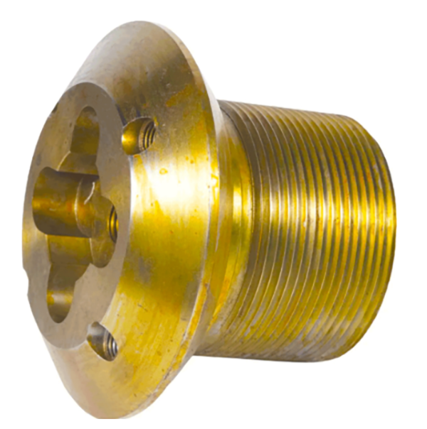
This paper provides a detailed introduction to the locking nut component of cone crushers. As an important fastening component, it is mainly used to secure key assemblies such as the main shaft, fixed cone liner, or adjustment ring. It can realize functions including secure fixation, load distribution, and maintaining the crushing gap in cooperation with the adjustment ring. Its composition and structure include the nut body, threaded bore, locking mechanism (such as locking holes, set screws, and tapered surfaces), flange or shoulder, and wrench flat faces, with each part having a specific design and function. In terms of casting process, large-sized locking nuts often use gray cast iron, ductile iron, or cast steel, going through steps such as material selection, pattern making, molding, melting and pouring, cooling and cleaning, and heat treatment. The machining and manufacturing process covers steps like rough machining, machining of locking features, finish machining, surface treatment, and assembly with locking components. Quality control includes measures such as material testing, dimensional accuracy checks, thread quality inspection, locking performance testing, and non-destructive testing, ensuring that the component has good wear resistance, anti-loosening performance, and structural rigidity in high-vibration environments, thus guaranteeing the stable operation of the crusher.
This paper provides a detailed overview of the cone crusher pinion, a critical transmission component that meshes with the bull gear to transfer motor power to the eccentric assembly, enabling the moving cone's oscillating motion. It elaborates on the pinion's functions, including power transmission, torque amplification, and precision meshing. The composition and structure are detailed, consisting of gear teeth, shaft body, bearing journals, shoulders/collars, lubrication holes, and keyway/spline, along with their structural characteristics. For large-scale pinions, the casting process is described, covering material selection, pattern making, molding, melting and pouring, cooling and shakeout, heat treatment, and inspection. For forged pinions, the machining and manufacturing process is outlined, including forging, rough machining, heat treatment, finish machining, and deburring/polishing. Additionally, quality control measures are specified, such as material validation, dimensional accuracy checks, hardness and microstructure testing, dynamic performance testing, non-destructive testing, and final inspection. These processes ensure the pinion achieves the required strength, precision, and durability, guaranteeing reliable power transmission in demanding crushing operations
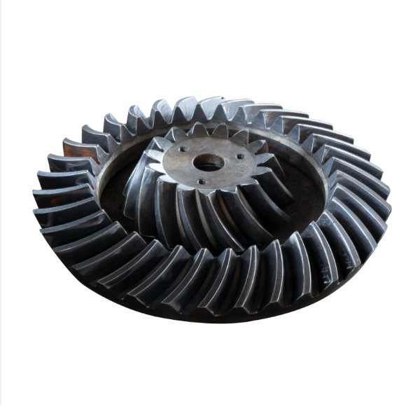
This paper provides a detailed account of the cone crusher gear, a core transmission component that transfers motor power to the eccentric shaft, driving the moving cone's oscillation. It fulfills key roles in power transmission, speed regulation, and torque amplification, requiring high strength, wear resistance, and precision. The gear's composition and structure are outlined, including the gear body (alloy steel, solid or hollow), teeth (involute profile with specific parameters), bore/shaft connection, hub/flange, lubrication grooves, and webs/ribs for large gears. For large bull gears, the casting process is detailed: material selection (ZG42CrMo), pattern making, molding, melting, pouring, cooling, and heat treatment. The machining process covers rough machining, tooth cutting (hobbing or shaping), hardening heat treatment (carburizing, quenching, tempering), finish machining (grinding), and deburring. Quality control measures include material testing (chemical analysis, tensile and impact tests), dimensional checks (CMM, gear measuring center), hardness and microstructure testing, dynamic performance testing (mesh and load tests), and non-destructive testing (MPT, UT). These ensure the gear meets precision, strength, and durability requirements, guaranteeing reliable operation in heavy-duty crushing scenarios.