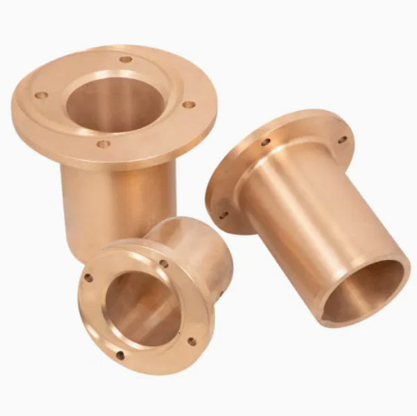
The cone crusher countershaft bushing, a critical bearing component between the countershaft and its housing, functions in load support (bearing radial and axial loads), friction reduction (minimizing energy loss at 500–1500 rpm), alignment maintenance (ensuring concentricity), and contamination protection. It requires excellent wear resistance, low friction, and dimensional stability. Structurally, it is a cylindrical or flanged sleeve comprising a bushing body (bearing bronze like ZCuSn10Pb1, babbitt metal, or steel-backed bimetallic materials), inner bearing surface (Ra0.8–1.6 μm with oil grooves), outer surface (interference fit with housing), optional flange, lubrication features (oil grooves and holes), and optional thrust faces. Its wall thickness ranges from 5–20 mm. For bronze bushings, the manufacturing process includes material selection, casting (centrifugal for cylindrical ones, sand casting for complex shapes), heat treatment (annealing at 500–600°C), and machining (rough and finish machining, oil groove machining). Bimetallic bushings involve steel shell preparation, bearing layer application (sintering or roll bonding), and final machining. Quality control covers material testing (chemical composition and hardness), dimensional checks (CMM and roundness tester), microstructural analysis, performance testing (friction coefficient and wear), and fit checks. These ensure the bushing provides precision, wear resistance, and low friction for efficient power transmission in cone crushers
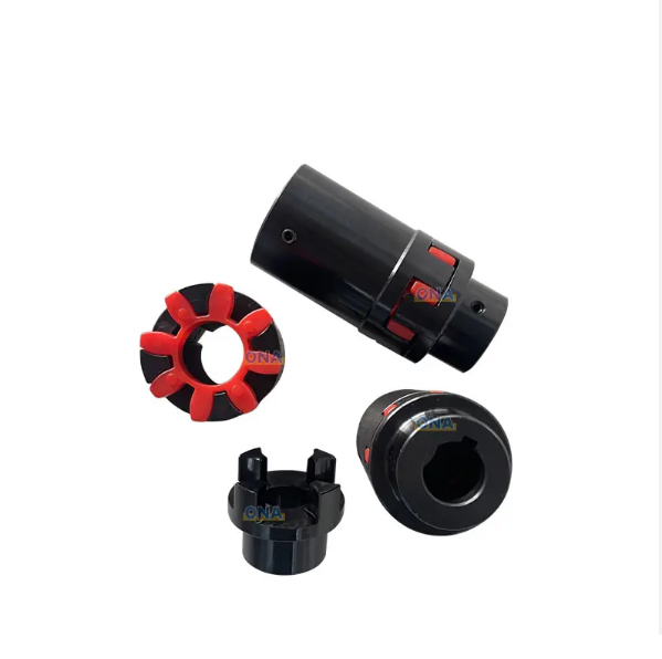
The cone crusher countershaft coupling, a critical power transmission component connecting the countershaft to the main drive system, plays key roles in torque transmission (transferring rotational power to drive the crushing motion), misalignment compensation (accommodating minor axial, radial, or angular misalignments), vibration damping (absorbing shock from load changes), and optional overload protection (via shear pins or friction discs). It requires high torsional strength, fatigue resistance, and flexibility for operation at 500–1500 rpm. Structurally, it is a flange-type or sleeve-type assembly consisting of coupling hubs (high-strength cast or forged steel with keyways/splines), a flexible element (rubber/elastomer discs, gear teeth, or pin and bushing), flange plates, fasteners, and optional shear pin holes. The coupling hubs are manufactured via casting: material selection (ZG35CrMo), pattern making (with shrinkage allowances), molding (resin-bonded sand mold), melting and pouring (controlled temperature and flow rate), cooling and shakeout, and heat treatment (normalization and tempering). The machining and manufacturing process includes hub machining (rough and finish machining), flexible element manufacturing (molding for rubber elements, gear cutting for gear-type elements), flange plate machining, assembly, and surface treatment. Quality control involves material testing (chemical composition and tensile strength), dimensional accuracy checks (CMM and fixture gauges), mechanical property testing (hardness and torsional testing), non-destructive testing (MPT and UT), and functional testing (misalignment and overload testing). These ensure the countershaft coupling enables reliable power transmission and stable cone crusher operation in mining and aggregate processing
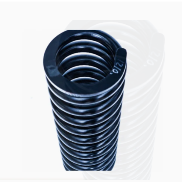
The cone crusher spring, a crucial safety and buffering component installed around the upper frame or between the adjustment ring and base, mainly functions in overload protection (absorbing impact energy to prevent damage from foreign objects), vibration damping (reducing noise and extending component life), providing reset force (restoring positions post-overload), and applying preload (maintaining stable operation). It requires high fatigue resistance, elastic limit, and corrosion resistance, operating under 50–80% of ultimate compressive strength preload. Structurally, it is a helical compression spring consisting of a spring coil (high-carbon spring steel wire like 60Si2MnA, 20–80 mm diameter), end faces (ground flat for stability), spring diameter (OD 150–500 mm, ID, with 20–100 mm pitch), optional hooks/connections, and surface coating (zinc plating, epoxy, etc.). Its design features a spring rate of 50–200 kN/mm for large crushers. The manufacturing process (wire forming, no casting) includes material selection and preparation (inspecting and straightening high-carbon spring steel wire), coiling (using CNC machines to control pitch, diameter, and coil number), heat treatment (quenching and tempering to achieve HRC 45–50 hardness), and end processing (grinding ends flat and deburring). For multi-spring systems, assembly involves selection/matching, mounting plate installation, and preload setting. Quality control covers material testing (chemical composition and tensile strength), dimensional checks (CMM for coil parameters and spring rate testing), mechanical property testing (hardness and fatigue testing), non-destructive testing (MPT and UT for defects), and corrosion resistance testing (salt spray testing). These ensure the spring reliably protects against overload and dampens vibration, maintaining stable crusher operation in harsh environments
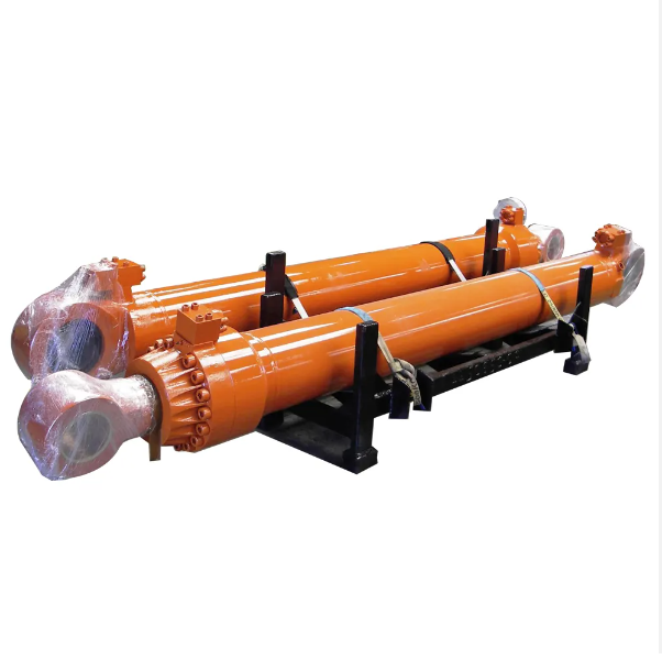
This paper details the safety cylinder (release cylinder) of cone crushers, a core safety component protecting the equipment from overloads by enabling the moving cone to displace via hydraulic oil release and reset. It elaborates on its composition (cylinder body, piston, sealing assembly, etc.) and structure, then outlines the casting process (material selection, mold making, melting, heat treatment, inspection), machining process (rough/finish machining, surface treatment, assembly), and quality control measures (raw material, machining accuracy, hydraulic performance, fatigue life, and factory inspections). The safety cylinder's design, craftsmanship, and quality control are crucial for its reliable operation and the crusher's longevity