Detailed Introduction to the Compound Cone Crusher
1. Overview and Working Principle of the Compound Cone Crusher
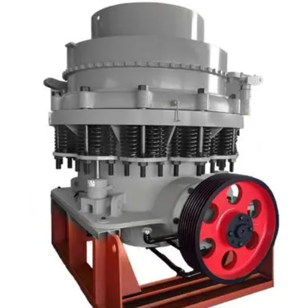
The compound cone crusher (also known as the multi-cavity cone crusher) is an advanced crushing equipment designed for medium to fine crushing of hard materials such as ore, rock, and aggregate. It integrates the advantages of traditional spring cone crushers and hydraulic cone crushers, featuring a multi-stage crushing cavity design that allows for adjustable crushing stages (from 2 to 4 stages) in a single unit. This design eliminates the need for multiple crushers in a production line, reducing space requirements and energy consumption.
The working principle is based on the "lamination crushing" mechanism: materials are squeezed, bent, and impacted between the rotating movable cone and the fixed cone (concave). The movable cone, driven by an eccentric shaft sleeve, performs oscillating motion, causing the crushing cavity to alternately expand and contract. The multi-cavity structure enables materials to undergo gradual crushing through different stages (coarse, medium, fine) as they move downward, resulting in uniform particle sizes and high cubicity in the final product.
2. Composition and Structure of the Compound Cone Crusher
The compound cone crusher consists of several key assemblies, each with specific components and functions:
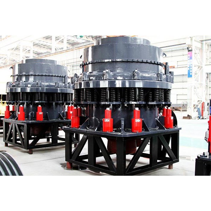
2.1 Main Frame Assembly
Frame Body: A heavy-duty cast steel (ZG270-500) structure that supports all internal components. It has a cylindrical or conical shape with a top flange for mounting the adjustment ring and a bottom base for fixing to the foundation. The frame thickness ranges from 50–150 mm, depending on the crusher size.
2.2 Crushing Assembly
Fixed Cone (Concave): A multi-section annular liner (2–4 segments) made of wear-resistant materials, mounted on the upper frame. Each segment corresponds to a crushing stage (coarse to fine), with varying cavity profiles (angle, depth) to control particle size.
2.3 Transmission Assembly
2.4 Adjustment and Safety Assemblies
Safety Device: A combination of hydraulic overload protection and spring buffers. When uncrushable materials enter the cavity, hydraulic pressure rises, triggering a relief valve to lift the fixed cone, expel the material, and reset automatically.
Lubrication System: An independent thin oil lubrication system with pumps, coolers, and filters that circulates oil (ISO VG 46) to bearings and gears, maintaining temperatures below 60°C.
2.5 Dustproof Assembly
3. Casting Processes for Key Components
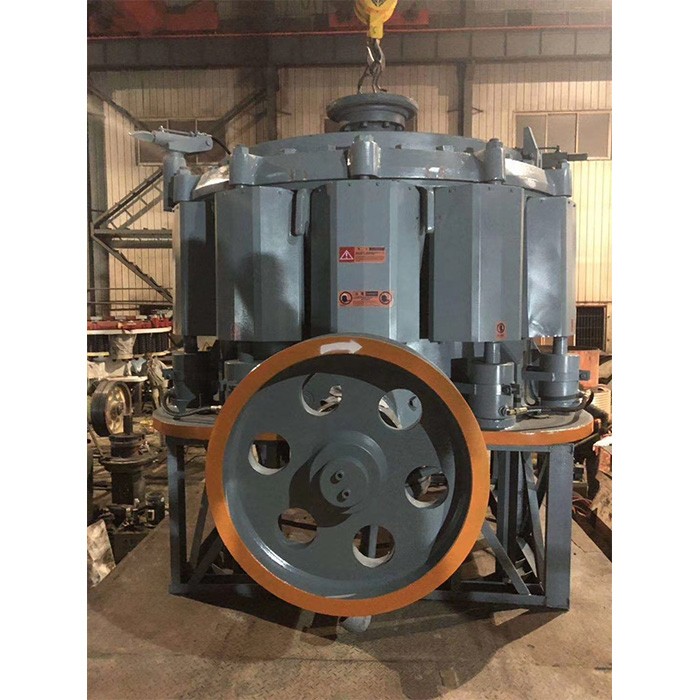
3.1 Frame Body (ZG270-500 Cast Steel)
Pattern Making: A full-scale wooden or metal pattern is created, including ribs, flanges, and oil passages. Shrinkage allowances (1.2–1.5%) are added.
3.2 Eccentric Shaft Sleeve (ZG35CrMo Cast Steel)
3.3 Movable Cone Body (42CrMo Forging)
4. Machining Processes
4.1 Frame Body
4.2 Eccentric Shaft Sleeve
4.3 Movable Cone
5. Quality Control Processes
Crushing Test: A 24-hour continuous run with standard aggregate (e.g., granite) checks production capacity, particle size distribution, and component wear.
The compound cone crusher’s robust structure, multi-cavity design, and precise manufacturing ensure high efficiency, reliability, and versatility in mining, construction, and aggregate processing applications