1. Ball mill Introduction
Ball mill is the key equipment for crushing materials after crushing.
Ball mill is one of the high-fine grinding machines widely used in industrial production, and there are many types,such as tube ball mill, rod ball mill, cement ball mill, superfine laminated mill, hand ball mill, horizontal ball mill,Ball mill bearing bush, energy-saving ball mill, overflow ball mill, ceramic ball mill, lattice ball mill.
The ball mill is suitable for grinding various ores and other materials. It is widely used in mineral processing, building materials and chemical industries. And it can be divided into dry and wet grinding methods. According to the different ways of discharging, it can be divided into two types: grid type and overflow type. According to the shape of the cylinder, it can be divided into four types: short tube ball mill, long tube ball mill, tube mill and cone mill.
型号规格 | MQS | MQS | MQS | MQS |
0909 | 0918 | 1212 | 1224 | 1515 | 1530 | 2122 | 2130 |
图 号 | K9272 | K9273 | K9261 | K9260 | K92513 | K92514 | K9245 | K92411 |
筒体直径mm | 900 | 1200 | 1500 | 2100 |
筒体长度mm | 900 | 1800 | 1200 | 2400 | 1500 | 3000 | 2200 | 3000 |
有效容积m3 | 0.5 | 1 | 1.2 | 2.4 | 2.5 | 5 | 6.6 | 9 |
最大装球量t | 0.96 | 1.92 | 2.4 | 4.8 | 5 | 10 | 15 | 20 |
工作转速r/min | 39.2 | 31.3 | 29.2 | 23.8 |
产量t/h | 0.22~1.07 | 0.44~2.14 | 0.17~4.0 | 0.4~5.8 | 1.4~4.3 | 2.8~9 | 按工艺条件定 |
主电机 | 型 号 | Y225S-8 | Y225M-8 | Y250M-8 | Y315S-8 | JR115-8 | JR125-8 | JR128-8 | JR137-8 |
功率 kW | 17 | 22 | 30 | 55 | 60 | 95 | 155 | 210 |
转速r/min | 720 | 730 | 725 | 730 | 735 |
电 压V | 380 |
机器外形尺寸 | 长m | 4.75 | 5.00 | 5.2 | 6.5 | 5.77 | 7.6 | 8 | 8.8 |
宽m | 2.21 | 2.28 | 2.8 | 3.3 | 4.7 |
高m | 2.05 | 2.54 | 2.7 | 4.4 |
机器总重量t | 4.62 | 5.34 | 11.4 | 13.43 | 1.39 | 1.74 | 42.2 | 45 |
备 注 | 机器总重不含电机重 |
型号规格 | MQG | MQG | MQG | MQG | MQG |
0909 | 0918 | 1212 | 1224 | 1515 | 1530 | 2122 | 2714 |
图 号 | K9270 | K9271 | K9263 | K9262 | K92510 | K92511 | KY9241 | K92111 |
筒体直径mm | 900 | 1200 | 1500 | 2100 | 2700 |
筒体长度mm | 900 | 1800 | 1200 | 2400 | 1500 | 3000 | 2200 | 1450 |
有效容积m3 | 0.5 | 1 | 1.2 | 2.4 | 2.5 | 5 | 6.65 | 2.87 |
最大装球量t | 0.96 | 1.92 | 2.4 | 4.8 | 4 | 8 | 14 | 3 |
工作转速r/min | 39.2 | 31.3 | 29.2 | 23.8 | 21.1 |
产量t/h | 0.165~0.8 | 0.33~1.6 | 0.16~2.6 | 0.26~6.15 | 1~3.5 | 2~6.8 | 5~29 | 3 |
主电机 | 型 号 | Y225S-8 | Y225M-8 | JQO282-8 | JQO292-8 | JR115-8 | JR125-8 | YR355M-8 | Y280M-6 |
功率 kW | 18.5 | 22 | 30 | 55 | 60 | 95 | 160 | 55 |
转速r/min | 730 | 725 | 730 | 980 |
电 压V | 380 |
机器外形尺寸 | 长m | 3.12 | 3.62 | 5.1 | 6.5 | 5.655 | 7.48 | 9.2 | 6.315 |
宽m | 2.21 | 2.23 | 2.8 | 3.26 | 3.3 | 4.9 | 3.562 |
高m | 2.02 | 2.5 | 2.7 | 4.4 | 4.519 |
机器总重量t | 4.39 | 5.36 | 10.5 | 12.545 | 13.48 | 18 | 47 | 22.6 |
备 注 | 机器总重不含电机重 |
型号规格 | MQY | MQY | MQY | MQY | MQY |
3245 | 3254 | 3260 | 3645 | 3650 | 3660 | 3690 | 4060 | 4561 | 5164 |
图 号 | K9227 | K92211 | K92214 | K9217 | K92111 | K9219 | K92113 | K9280 | K9281 | K9291 |
筒体直径mm | 3200 | 3600 | 4000 | 4572 | 5100 |
筒体长度mm | 4500 | 5400 | 6000 | 4500 | 5000 | 6000 | 9000 | 6000 | 6100 | 6400 |
有效容积m3 | 32.8 | 39.5 | 43.7 | 41 | 46.2 | 55 | 83 | 69.9 | 93.3 | 117.8 |
最大装球量t | 61 | 73 | 81 | 76 | 86 | 102 | 163 | 113 | 151 | 218 |
工作转速r/min | 18.5 | 17.5 | 17.3 | 16.8 | 15.1 | 13.8 |
产量t/h | 按工艺条件定 |
主电机 | 型 号 | TDMK 630-36 | TM1000-36/2600 | TM1250-40/3250 | TM1800 -30/2600 | TDMK 1500-30/2600 | TDMK 2200-32 | TM 2600-30 |
功率 kW | 630 | 1000 | 1250 | 1800 | 1500 | 2200 | 2600 |
转速r/min | 167 | 150 | 200 | 187.5 | 200 |
电 压V | 6000 |
机器外形尺寸 | 长m | 14.6 | 15.8 | 15.084 | 15.0 | 17.157 | 17.0 | 19.187 | 16.555 | 16.563 | 14.0 |
宽m | 6.7 | 7.2 | 7.755 | 7.7 | 9.793 | 8.418 | 9.213 | 8.3 |
高m | 5.15 | 5.196 | 6.3 | 6.326 | 6.3 | 7.493 | 7.429 | 8.132 | 9.0 |
机器总重量t | 112 | 121 | 138.2 | 135 | 145 | 154 | 212 | 213 | 272 | 290 |
备 注 | 机器总重不含电机重 |
2. Ball mill Working principle
The ball mill is composed of a horizontal cylinder, a hollow shaft for feeding and discharging materials, and a grinding head. The cylinder is a long cylinder with a grinding body installed in the cylinder. The cylinder is made of steel plate. The steel liner is fixed to the cylinder. Generally, the grinding body is a steel ball, which is packed into the cylinder according to different diameters and a certain proportion. The grinding body can also be made of steel. Choose according to the particle size of the grinding material. The material is loaded into the cylinder by the hollow shaft at the feed end of the ball mill. When the cylinder of the ball mill rotates, the grinding body is attached to the cylinder liner due to inertia, centrifugal force and friction. Carried away by the cylinder, when brought to a certain height, it will be thrown down due to its own gravity. The falling grinding body will crush the material in the cylinder like a projectile.
The material enters the first chamber of the mill uniformly through the feeding device through the hollow shaft of the feeding device. There is a step liner or a corrugated liner inside the first chamber of the mill. The chamber is equipped with various specifications of steel balls. Falling after the height has a heavy blow and grinding effect on the material. After the material reaches the rough grinding in the first warehouse, it enters the second warehouse through the single-layer partition board. The warehouse is lined with flat liners and steel balls to further grind the materials. The powder is discharged through the unloading grate to complete the grinding operation.
When the barrel is rotating, the grinding body also slips off. During the sliding process, the material is ground. In order to effectively use the grinding effect, when grinding the material with larger particle size, the grinding body is fine. Divided into two sections by a partition board, it becomes a double silo. When the material enters the first silo, it is crushed by the steel ball. When the material enters the second silo, the steel section grinds the material, and the ground qualified material is hollow from the discharge end. When the shaft is discharged to grind materials with small feed particles, such as sand No. 2 slag and coarse fly ash, the barrel of the mill can be formed as a single-silo barrel mill without a partition, and the grinding body can also be made of steel.
The raw materials are fed into the hollow cylinder through the hollow shaft journal for grinding. The cylinder is equipped with various diameter grinding media (steel balls, steel rods or gravel, etc.). When the cylinder rotates around the horizontal axis at a certain speed, the medium and raw materials contained in the cylinder will be separated from the cylinder as the cylinder reaches a certain height under the action of centrifugal force and frictional force. The body wall is projected to fall or roll down, crushing the ore due to the impact force. At the same time, during the rotation of the mill, the sliding movement between the grinding media also has a grinding effect on the raw materials. The ground material is discharged through the hollow journal.
3. Ball mill loading
The main function of the steel ball in the ball mill is to impact and crush the material, and it also plays a certain role in grinding. Therefore, the purpose of grading steel balls is to meet these two requirements. The crushing effect directly affects the grinding efficiency and ultimately affects the output of the ball mill. Whether the crushing requirements can be met depends on whether the gradation of the steel balls is reasonable, including the size of the steel balls, the number of ball diameters, and the ball positions of various specifications. Proportion and so on.
To determine these parameters, you need consider the size of the ball mill, the internal structure of the ball mill, the product fineness requirements and other factors, the characteristics of the grinding material (easy to grind, particle size, etc.).
In order to effectively crush the materials, several principles must be followed when determining the gradation:
First of all, the steel ball must have enough impact force to make the steel ball of the ball mill have enough energy to crush the particulate material, which is directly related to the maximum ball diameter of the steel ball.
Secondly, the steel ball must have enough impact times on the material, which is related to the filling rate of the steel ball and the average ball diameter. When the filling amount is constant, under the premise of ensuring sufficient impact force, try to reduce the diameter of the grinding body and increase the number of steel balls to increase the number of impacts on the material to improve the crushing efficiency.
Finally, the material has enough residence time in the mill to ensure that the material is fully crushed, which requires the steel ball to have a certain ability to control the flow rate of the material.
The so-called two-stage ball grading method is to use two different sizes of steel balls with a large difference in diameter. The theoretical basis is that the gaps between the large balls are filled by small balls to fully increase the packing density of the steel balls. In this way, on the one hand, the impact capacity and the number of impacts of the mill can be improved, which is in line with the functional characteristics of the grinding body. On the other hand, the higher bulk density enables the material to obtain a certain grinding effect. In the two-stage ball distribution, the main function of the big ball is to impact and crush the material. The first function of the small ball is to fill the gap between the big balls and increase the bulk density of the grinding body to control the material flow rate and increase the grinding capacity; It plays the role of energy transfer and transfers the impact energy of the big ball to the material; the third is to squeeze out the coarse particles in the gap and place it in the impact area of ??the big ball.
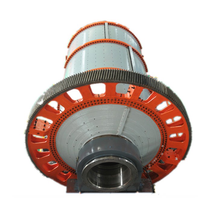
4. Ball mill Mechanical structure
The ball mill is composed of feeding part, discharging part, rotating part, transmission part (reducer, small transmission gear, motor, electric control) and other main parts. The hollow shaft is made of cast steel, the inner lining is removable, the large rotary gear is processed by casting hobbing, and the cylinder is inlaid with a wear-resistant liner, which has good wear resistance. The machine runs smoothly and works reliably.
The main body of the ball mill includes a cylinder, in which a lining made of wear-resistant material is inserted in the cylinder, there are bearings that carry the cylinder and maintain its rotation, and there are driving parts such as a motor, transmission gears, pulleys, and V-belts.
As for the parts called blades, they are generally not the main components. The internal spiral blades in the component inlet of the feed end can be called internal spiral blades, and the internal spiral blades in the component outlet of the discharge end can also be called internal spiral blades.
In addition, if a screw conveyor is used in the auxiliary equipment at the discharge end, there will be parts called spiral blades in the equipment, but strictly speaking, it is no longer a part of the ball mill.
According to the material and discharge method, dry ball mill and wet grid ball mill can be selected. The energy-saving ball mill adopts self-aligning double-row radial spherical roller bearings with low running resistance and significant energy-saving effect. In the barrel part, a section of conical barrel is added at the discharge end of the original barrel, which not only increases the effective volume of the mill, but also makes the medium distribution in the barrel more reasonable. This product is widely used for material grinding in non-ferrous metals, ferrous metals, non-metallic mineral processing plants, chemical and building materials industries.
5. Ball mill accessories
Ball mill gear
Ball mill accessories include ball mill gear, ball mill pinion, ball mill hollow shaft, ball mill gear ring, ball mill gear ring, ball mill steel ball, ball mill compartment plate, ball mill transmission device, ball mill bearing, ball mill end lining, and so on.
The material selection of the big gear of the ball mill:
According to the working conditions of large gears, large gears are usually made of the following materials:
(1) Medium carbon structural steel
(2) Medium carbon alloy structural steel
(3) Carburized steel
(4) Nitrided steel
The structure of the big gear of the ball mill has a variety of different shapes due to different usage requirements, but from the technological point of view, the gear can be regarded as composed of two parts: the ring gear and the wheel body. According to the distribution of gear teeth on the ring gear, it can be divided into straight teeth, helical teeth, and herringbone teeth.


Ball mills are critical equipment in industries such as mining, building materials, and metallurgy. Their manufacturing processes and quality control directly affect operational efficiency, service life, and safety. Below is a detailed overview of the manufacturing process and quality control measures for ball mills:
A ball mill consists of core components including the cylinder, end caps, hollow shafts, transmission system (gears, couplings, etc.), and liners. The manufacturing process involves staged processing of individual components followed by final assembly.
The cylinder is the main body of the ball mill, responsible for holding grinding media (e.g., steel balls) and materials. It requires high strength, rigidity, and wear resistance.
Material Selection: Typically uses Q345R (low-alloy steel for pressure vessels) or Q235B (carbon structural steel). The thickness (16–50mm) is determined based on equipment specifications and operating conditions (e.g., grinding hardness, corrosiveness).
Processing Steps:
Steel Plate Cutting: CNC flame cutting or plasma cutting is used to cut steel plates into 扇形坯料 (sector blanks) matching the unfolded dimensions of the cylinder, with welding allowances reserved.
Rolling and Forming: A large rolling machine bends the blanks into a cylindrical shape, ensuring the roundness error ≤1mm/m and straightness error ≤0.5mm/m.
Welding Seams: Submerged arc welding is applied to longitudinal seams (axial joints of the cylinder). After welding, a 24-hour aging treatment is performed to eliminate welding stress. For cylinders longer than the steel plate width, circumferential seams (radial joints) are welded using symmetric welding to minimize deformation.
Roundness Calibration: A rounding machine corrects the ellipticity of the welded cylinder to ensure assembly accuracy with end caps.
End caps are located at both ends of the cylinder, connecting the cylinder to the hollow shafts. They must withstand the impact of grinding media and the equipment’s self-weight.
The hollow shaft supports the rotating cylinder and requires high toughness and wear resistance.
Includes large gears, small gears, and couplings, requiring stable transmission and high precision.
Large Gear:
Material: ZG35SiMn (cast steel) or 42CrMo forging, with tooth surface quenching (hardness: 35–45HRC).
Processing: After casting/forging, rough turning is performed, followed by quenching and tempering. Precision turning of the outer circle and end face is done, then hobbing to form teeth. Finally, tooth surface quenching and grinding are applied (accuracy: Grade 6 per GB/T 10095.1-2008).
Small Gear:
Material: 40CrNiMoA forging, with overall quenching and tempering followed by tooth surface quenching (hardness: 45–50HRC).
Processing: After forging, rough machining is done, followed by heat treatment, precision turning of the journal, hobbing, and final grinding (same accuracy as the large gear).
Liners protect the cylinder from wear by grinding media and materials, requiring high wear resistance.
Component Pre-assembly: Inspect dimensions of components (e.g., cylinder roundness, end cap spigot tolerance) and clean oil stains and burrs on machined surfaces.
Cylinder and End Cap Assembly: Align end caps with cylinder flanges, tighten bolts evenly (in diagonal order) or weld them (with post-welding flaw detection).
Hollow Shaft Installation: Connect the hollow shaft to the end cap bearing seat via hot fitting (heating the bearing seat to 100–150°C) or bolts, ensuring coaxiality error of the two hollow shafts ≤0.1mm/m.
Transmission System Assembly:
The large gear is connected to the cylinder via hot fitting or bolts, ensuring the gear end face perpendicularity to the cylinder axis ≤0.05mm/m.
The small gear is connected to the reducer output shaft. Adjust the meshing clearance (0.2–0.4mm) and contact pattern (≥60% along tooth height, ≥70% along tooth length) of the large and small gears.
Main Bearing Installation: Fix the bearing seat to the foundation, adjust the fitting clearance between the hollow shaft and bearing (0.15–0.3mm for sliding bearings, as per specifications for rolling bearings), and ensure bearing seat levelness error ≤0.05mm/m.
Test Run:
No-load Test: Run for 4 hours, checking bearing temperature (≤65°C), gear meshing noise (≤85dB), and cylinder vibration (amplitude ≤0.1mm).
Load Test: Gradually load to 50%, 80%, and 100% of the design load, with a total running time of 8 hours, confirming no abnormalities in components.
Quality control spans the entire manufacturing process, with three-level checks: material inspection, process inspection, and finished product inspection.
Raw Material Inspection:
Steel plates, forgings, and castings must provide material certificates (chemical composition, mechanical properties). Sampling for spectral analysis (to confirm element content) and tensile tests (to detect tensile strength and yield strength) is required.
High-chromium cast iron liners are tested for hardness (≥HRC58) and impact toughness (≥3J/cm²). High-manganese steel is inspected for metallographic structure after water toughening (no network carbides).
Machining Accuracy Inspection:
Cylinder: Laser roundness meters check roundness; straightedges and feeler gauges check straightness.
Hollow Shaft: Dial indicators measure journal roundness (≤0.01mm) and cylindricity (≤0.02mm); coordinate measuring machines check coaxiality.
Gears: Gear detectors measure pitch error (≤0.02mm) and tooth profile error (≤0.015mm); coloring method checks meshing contact patterns.
Welding Quality Inspection:
100% non-destructive testing (UT for internal defects, MT for surface cracks) is performed on longitudinal and circumferential seams, with 100% weld qualification.
Mechanical property tests (tensile and bending tests) on welded joints ensure strength not lower than the base material.
Heat Treatment Inspection:
After quenching and tempering of forgings and gears, hardness testers check surface hardness (error ±5HBW); metallographic microscopes observe structures (e.g., tempered sorbite for quenched and tempered steel).
Strict adherence to these manufacturing and quality control processes ensures ball mills meet the requirements of "high efficiency, wear resistance, low energy consumption, and safety," extending their service life (typically ≥10 years, with liner replacement cycles of 6–12 months)