This paper elaborates on the sheave (pulley) of cone crushers, a key power transmission component that transfers rotational motion from the motor to the countershaft via a drive belt, adjusts countershaft speed, and absorbs vibration. It details its composition and structure, including the sheave body, V-grooves, hub, rim, and web. The casting process for the sheave body is outlined, covering material selection (gray cast iron), pattern making, molding, melting, pouring, heat treatment, and inspection. It also describes the machining process (rough/finish machining, surface treatment) and assembly features. Additionally, quality control measures are specified, such as material testing, dimensional accuracy checks, balancing, functional testing, and surface quality inspection. These processes ensure the sheave enables efficient power transmission, reducing belt wear and enhancing the cone crusher’s operational reliability
Detailed Introduction to the Cone Crusher Sheave Component
1. Function and Role of the Cone Crusher Sheave
The sheave (also called a pulley) is a critical power transmission component in cone crushers, responsible for transferring rotational motion from the motor to the countershaft via a drive belt (V-belt or wedge belt). Its key functions include:
Transmitting torque from the motor to the crusher’s transmission system, enabling the rotation of the countershaft and subsequent operation of the crushing mechanism.
Adjusting the speed of the countershaft through diameter variation (in conjunction with motor pulley sizes), optimizing crushing efficiency for different materials.
Absorbing minor vibration and shock from the motor, reducing impact on the crusher’s transmission components.
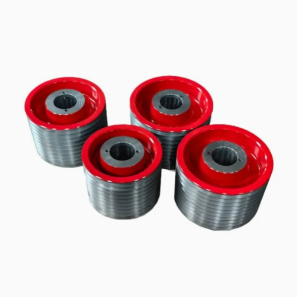
2. Composition and Structure of the Sheave
Cone crusher sheaves are typically V-groove pulleys, designed to match the drive belt profile. Their structure includes:
Sheave Body: The main cylindrical or conical structure with grooves for belt placement. It is usually a one-piece casting or forging, with a hub at the center for mounting to the countershaft.
V-Grooves: Multiple circumferential grooves (number matching the belt count, e.g., 2–6 grooves) with a 34°–40° angle, designed to grip the V-belt sides and transmit torque via friction. Groove depth and width are standardized (e.g., SPZ, SPA, SPB series) to match belt dimensions.
Hub: A central cylindrical projection with a bore for mounting onto the countershaft. It may feature a keyway, set screw holes, or taper lock to secure the sheave to the shaft, preventing slippage during rotation.
Rim: The outer edge of the sheave body, reinforcing the structure and limiting belt lateral movement. It may include lightening holes (for large sheaves) to reduce weight and inertia.
Web: The radial structure connecting the hub to the rim, providing mechanical strength while minimizing weight. It may be solid (for small sheaves) or ribbed (for large sheaves) to enhance rigidity.
3. Casting Process for the Sheave Body
Most sheaves are cast for cost-effectiveness and complex geometry, with the following steps:
Material Selection: Gray cast iron (HT250 or HT300) is preferred for its good castability, wear resistance, and vibration damping. For heavy-duty applications, ductile iron (QT500-7) or cast steel (ZG270-500) is used for higher tensile strength.
Pattern Making: A wooden, metal, or 3D-printed pattern replicates the sheave’s geometry, including grooves, hub, and web. Shrinkage allowances (1–2%) and draft angles (2–3°) are added for mold removal.
Molding: Resin-bonded sand molds are formed around the pattern. Cores create the central bore and lightening holes (if present). The mold is cured to ensure dimensional stability.
Melting and Pouring: Cast iron is melted in an induction furnace at 1400–1450°C. Molten metal is poured into the mold via a gating system, with controlled speed to avoid turbulence and ensure complete filling of grooves.
Cooling and Shakeout: The casting cools slowly in the mold to reduce stress, then is removed via vibration. Risers and gates are cut off, and surface sand is cleaned.
Heat Treatment: Stress relief annealing (550–600°C for 2–3 hours) eliminates residual stresses, preventing warping during machining.
Casting Inspection: Visual checks for cracks, porosity, or incomplete grooves. Ultrasonic testing (UT) detects internal defects in critical areas (hub and web).
4. Machining and Manufacturing Process
Rough Machining:
The outer rim and hub are turned to remove excess material, establishing basic dimensions with 1–2 mm finishing allowance.
The central bore is rough-drilled and reamed to approximate size.
Finish Machining:
V-grooves are precision-turned using a lathe with a groove-cutting tool, ensuring angle (±0.5°), depth (±0.1 mm), and width (±0.05 mm) match belt specifications.
The hub bore is finish-ground to IT7 tolerance, with a surface roughness of Ra1.6 μm. Keyways are milled to standard dimensions (e.g., DIN 6885) with tight tolerances.
The sheave’s face is machined to be perpendicular to the bore axis (runout ≤0.05 mm) to prevent belt misalignment.
Surface Treatment:
Grooves are shot-blasted to remove burrs and improve friction with the belt.
The outer surface is painted or coated with anti-corrosive finish (e.g., zinc plating) for durability.
Assembly Features:
Taper lock bushings (if used) are pressed into the hub, with matching tapers to ensure secure shaft mounting.
Set screws are installed in threaded holes, with tips hardened to bite into the shaft and prevent slippage.
5. Quality Control Processes
Material Testing: Castings are analyzed for chemical composition (spectrometry) and mechanical properties (tensile strength, hardness: 180–240 HBW for HT250).
Dimensional Accuracy:
CMM (Coordinate Measuring Machine) verifies groove dimensions, bore diameter, and face runout.
Groove angle is checked with a protractor; pitch diameter (distance between groove centers) is measured to ensure belt alignment.
Balancing:
Dynamic balancing is performed for sheaves rotating above 1000 RPM, ensuring residual unbalance ≤10 g·mm/kg to reduce vibration.
Functional Testing:
Belt fit test: V-belts are installed to check groove engagement (no excessive tightness or looseness).
Torque test: The sheave is mounted on a test shaft and subjected to rated torque to verify no slippage or deformation.
Surface Quality:
Groove surfaces are inspected for cracks or sharp edges (via microscopy) that could damage belts.
Paint adhesion is tested with a cross-cut method (ISO 2409), requiring no peeling.
The sheave’s precise manufacturing and quality control ensure efficient power transmission, minimizing belt wear and maximizing the cone crusher’s operational reliability
In order to overcome the above shortcomings, Shilong provides a connecting structure of the transmission shaft and the pulley of the cone crusher that can be easily installed and removed. At the same time it can ensure that the connecting surface of the transmission shaft and the pulley will not be caused any damage when the transmission shaft is assembled and installed. The technical solution we adopted is a connecting structure between the transmission shaft and the pulley of the cone crusher, which includes the pulley and the transmission shaft. The center of the pulley has a shaft hole, and the connecting section of the transmission shaft is placed in the shaft hole. It has an expansion sleeve hole, which is coaxial with the shaft hole. The diameter of the expansion sleeve hole is larger than that of the shaft hole. The inner circumferential surface of the expansion sleeve hole and the outer circumferential surface of the connecting section of the transmission shaft enclose an expansion sleeve cavity. An expansion sleeve is arranged in the sleeve cavity. A pressure plate is fixed at the outer end of the pulley, and the center of the pressure plate is connected with the shaft head of the transmission shaft through a connecting bolt. The technical solution we adopted is a connection structure between the transmission shaft and the pulley of the cone crusher. The transmission shaft and the pulley are connected through an expansion sleeve arranged in the expansion sleeve cavity, eliminating the need for keyways and key pins in the traditional connection structure, especially "with centering High precision; easy installation, adjustment, and disassembly; high strength, stable and reliable connection; protection of equipment from damage when overloaded". In addition, the pressure plate fixed at the outer end of the pulley prevents impurities from entering the expansion cavity and polluting the expansion tight sleeve.