The hydraulic motor in a cone crusher is a key power component that converts hydraulic energy (from the hydraulic system) into mechanical rotational energy. It primarily drives auxiliary functions such as adjusting the crusher’s discharge setting (via moving the main shaft or adjusting the crushing gap) and controlling the safety cylinder’s reset after overload. Its high torque output and precise speed control ensure smooth adjustment of the crushing process, enhancing operational efficiency and adaptability to varying material properties.
Cone crusher hydraulic motors are typically high-pressure axial piston motors or gerotor motors, composed of the following core components:
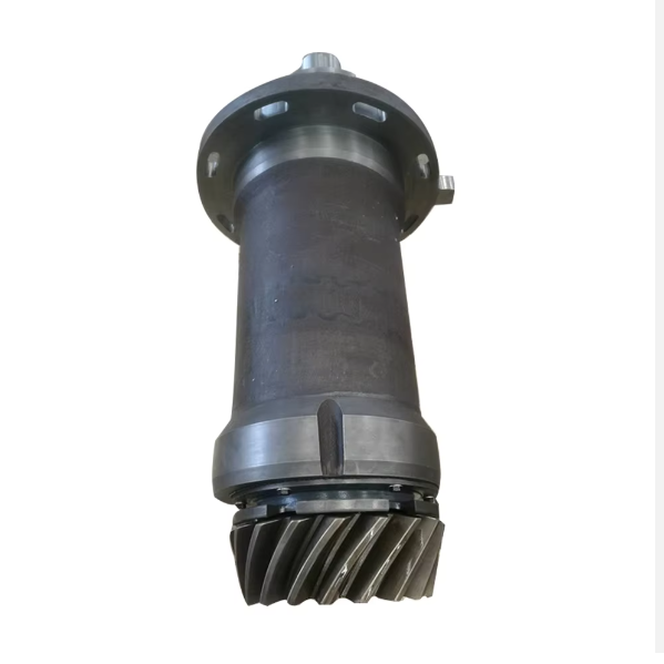
Motor Housing: A rigid outer casing that encloses internal parts and withstands system pressure. It is usually made of high-strength cast iron (HT300) or cast steel (ZG270-500), featuring ports for hydraulic oil inlet/outlet and mounting flanges for fixed installation.
Rotating Shaft (Output Shaft): Transmits rotational torque to connected components (e.g., adjustment gears). It is machined from alloy steel (40Cr) with high surface hardness (50–55 HRC) to resist wear, and its end is often equipped with a keyway or spline for torque transfer.
Piston Assembly (for Axial Piston Motors): Consists of pistons, cylinder block, and swashplate. Pistons slide in the cylinder block’s bores, driven by hydraulic pressure; the swashplate’s angle determines piston stroke and output speed. For gerotor motors, this is replaced by an inner rotor (with fewer teeth) and outer rotor (with more teeth) that mesh to create fluid chambers.
Valve Plate: Controls the direction of hydraulic oil flow into and out of the cylinder block, ensuring continuous rotation. It is made of wear-resistant materials (e.g., bronze alloy or hardened steel) and precision-ground to minimize leakage.
Sealing Components: Include O-rings, piston seals, and shaft seals (e.g., lip seals) to prevent internal and external oil leakage. They are typically made of nitrile rubber (NBR) or polyurethane (PU) for resistance to high pressure and hydraulic oil.
Bearings: Support the rotating shaft and reduce friction. Tapered roller bearings or deep groove ball bearings are commonly used, selected for high radial and axial load capacity.
Spring Mechanism (in Some Models): Maintains contact between the valve plate and cylinder block, ensuring effective sealing even under pressure fluctuations.
The motor housing, a critical cast component, undergoes the following casting steps:
Material Selection: Choose HT300 gray cast iron for its excellent castability, vibration damping, and machinability, or ZG270-500 cast steel for higher pressure resistance (up to 30 MPa).
Pattern and Mold Making: Create a wooden or metal pattern replicating the housing’s geometry, including oil ports, flanges, and internal cavities. Sand molds (resin-bonded for precision) are formed around the pattern, with cores to shape internal passages.
Melting and Pouring: For cast iron, melt in an induction furnace at 1400–1450°C, adjusting carbon (3.2–3.6%) and silicon (1.8–2.2%) content. Pour molten metal into the mold via a gating system to avoid turbulence, ensuring complete filling of thin-walled sections.
Cooling and Shakeout: Allow the casting to cool slowly in the mold to reduce internal stress, then remove sand via vibration. Trim risers and gates to achieve the rough shape.
Heat Treatment: Perform stress relief annealing on cast iron housings (550–600°C for 2–3 hours) to eliminate residual stress from casting. Cast steel housings may undergo normalizing (850–900°C) to refine grain structure.
Casting Inspection: Check for surface defects (cracks, sand holes) via visual inspection. Use ultrasonic testing (UT) to detect internal flaws, ensuring no pores or inclusions larger than φ2 mm in pressure-bearing areas.
Housing Machining:
Rough Machining: Use CNC lathes to turn the outer surface, flanges, and oil port threads, leaving 1–2 mm finishing allowance. Mill mounting holes and clean up internal cavities.
Finish Machining: Precision bore the inner cavity (for bearing and rotor installation) to IT7 tolerance, with surface roughness Ra1.6–3.2 μm. Tap oil ports to ensure tight sealing with hydraulic fittings.
Rotating Shaft Machining:
Forging: Heat 40Cr alloy steel billets to 1100–1200°C, forge into shaft blanks, then normalize to relieve stress.
Turning and Grinding: Rough turn the shaft, then precision grind the bearing journals and spline/keyway areas to IT6 tolerance. Surface hardness is achieved via quenching and tempering (50–55 HRC).
Piston and Cylinder Block Machining (for Axial Piston Motors):
Pistons are machined from high-strength aluminum alloy or steel, with precision-ground outer diameters (Ra0.8 μm) to fit cylinder bores.
Cylinder blocks are drilled for piston bores, with honed surfaces to ensure uniform oil distribution and minimal friction.
Assembly:
Press-fit bearings into the housing and mount the rotating shaft, ensuring proper axial clearance (0.03–0.08 mm).
Install the piston assembly, swashplate (or rotor set), and valve plate, verifying smooth rotation under manual testing.
Fit sealing components and connect hydraulic ports, then test for leaks under pressure (1.5 times the rated pressure for 30 minutes).
Material Testing: Verify chemical composition of castings and alloy steels via spectrometry. Test mechanical properties (tensile strength, hardness) to meet material standards.
Dimensional Accuracy: Use coordinate measuring machines (CMM) to inspect housing bore diameter, shaft runout, and piston/cylinder block clearances. Ensure keyways and splines meet tolerance requirements (±0.02 mm).
Pressure and Leakage Testing: Subject assembled motors to pressure testing (rated pressure + 50%) to check for leaks. Measure oil flow rate and pressure drop to confirm performance matches design specifications.
Performance Testing: Run the motor under rated speed and torque conditions to evaluate output accuracy, noise levels (<85 dB), and temperature rise (<40°C above ambient).
Fatigue Testing: Conduct 10,000+ cycles of start-stop operation under full load to assess durability of seals, bearings, and structural components.
By adhering to these processes, the hydraulic motor delivers reliable performance, ensuring precise control of cone crusher operations under heavy-duty conditions.
1. hydraulic system of the cone crusher Overload protection
At present, cone crushers are widely used in industries such as mining, construction, and refractory materials. It is used for various ores of crusher, due to the hardness and different properties of the material. Cone crushers will inevitably have overload failures during operation. This requires the cone crusher hydraulic system to have a good overload protection device to ensure safe and stable operation of the equipment, which not only ensures production but also reduces the failure rate of the equipment . The following are the advantages of the hydraulic system overload protection of the cone crusher.
a. It prevents the phenomenon of bending deformation, partial fracture of parts, and jamming of the transmission shaft.
b. It is not only convenient and accurate when controlling and adjusting the discharge port of the crusher, but also the hydraulic system can effectively ensure the safe operation of the equipment.
c. the hydraulic system can make the moving cone automatically move downwards when there is a foreign body in the crushing chamber. The system will automatically reset the moving cone when the foreign matter is discharged. Re-maintain the original discharge port position to continue working. No need to replace parts, economical and time-saving.
d. It is convenient for microcomputer operation and control, and easy to realize the automation of crushing process.
2. hydraulic system of the cone crusher Produce consequences
a. Impurities generated by oil oxidation: After the oil is oxidized at high temperature the oil temperature is too high, impurities such as gum and asphalt will be produced, which will block the small holes and gaps in the hydraulic components, causing the pressure valve to adjust the pressure and the flow rate of the flow valve to be unstable. And the direction valve is stuck and does not change direction, and the metal pipe is stretched and bent. Even rupture and many other faults.
b. The parts of the hydraulic system expand due to overheating: the oil temperature is too high, causing thermal deformation, making the gap between the relatively moving parts with different thermal expansion coefficients smaller, or even jamming, making the parts lose their working ability.
c. Accelerate the damage of seals: Too high oil temperature will cause the rubber seals to soften, swell and harden, cracks, etc., which will reduce their service life, lose sealing performance, cause leakage, and leakage will further heat up and increase temperature Elevated.
d. The viscosity of the hydraulic oil decreases: the oil temperature rises, the oil viscosity decreases, the leakage increases, and the volume efficiency is reduced. As the viscosity of the oil decreases, the oil film of the sliding valve and other moving parts becomes thinner and cut, and the friction resistance increases, resulting in increased wear, heating of the system, and temperature rise. Statistics show that the stable service life of oil will be reduced by 10 times every time the oil temperature increases by 15°C.
e. Reduced air separation pressure causes oil to overflow: the oil temperature rises, the oil air separation pressure decreases, and the dissolved air in the oil overflows, resulting in air pockets, resulting in a decrease in the working performance of the hydraulic system.
3. hydraulic system of the cone crusher Reasons for the increase
a. Unreasonable hydraulic system design: due to unreasonable selection of hydraulic component specifications in the hydraulic system; unreasonable piping design in the hydraulic system; redundant circuits or hydraulic components in the hydraulic system; unreasonable conditions such as no unloading circuit in the hydraulic system, Various malfunctions have occurred. Causes the system temperature to rise, which leads to an increase in oil temperature.
b.Improper selection of oil: the selected oil has improper viscosity, high viscosity, and large internal friction loss; if the viscosity is too low, the leakage will increase, both of which will cause heating and heating. In addition, because the pipelines in the system have not been cleaned or maintained for a long time, the inner wall of the pipeline supports the dirt, which increases the resistance when the oil flows, and also consumes energy to increase the oil temperature.
c. Severe pollution: The construction site environment is harsh. As the working hours of the machine increase, impurities and dirt are easily mixed in the oil. Contaminated hydraulic oil enters the matching gap of the pump, motor and valve, which will scratch and damage the matching surface The precision and roughness of the product increase leakage and oil temperature.
d. The oil level in the hydraulic oil tank is too low: If the amount of oil in the hydraulic oil tank is too small, the hydraulic system will not have enough flow to take away the heat generated by it, causing the oil temperature to rise.
e. Air mixed in the hydraulic system: The air mixed in the hydraulic oil will overflow from the oil and form bubbles in the low-pressure area. When it moves to the high-pressure area, these bubbles will be broken by the high-pressure oil and be rapidly compressed to release a large amount The heat causes the oil temperature to rise.
f. Oil filter blockage: When abrasive particles, impurities and dust pass through the oil filter, they will be adsorbed on the filter element of the oil filter, which will increase the oil absorption resistance and energy consumption, causing the oil temperature to rise.
g. The hydraulic oil cooling circulation system does not work well: usually, a water-cooled or air-cooled oil cooler is used to forcefully cool the oil temperature of the hydraulic system. Water-cooled coolers will reduce the heat dissipation coefficient due to dirty heat sinks or poor water circulation; air-cooled coolers will block the gaps in the heat sink of the cooler due to excessive oil pollution, making it difficult for fans to dissipate heat. Causes the oil temperature to rise.
h. The parts are severely worn: the gears of the gear pump, the pump body and the side plate, the cylinder block and the valve plate of the plunger pump and the motor, the cylinder hole and the plunger, the valve stem and the valve body of the reversing valve, etc. The gap is sealed, the wear of these components will cause the increase of internal leakage and the increase of oil temperature,
i. Ambient temperature is too high: the ambient temperature is high, the machine working time is too long, and some reasons which can cause the oil temperature to rise.
4. hydraulic system of the cone crusher Preventive measures
The increase in the temperature of the hydraulic oil of the cone crusher will cause a series of failures such as aging and deterioration of the seals of the cone crusher, shortening of the life, and loss of sealing performance. Therefore, it is necessary to implement preventive measures against excessively high hydraulic temperature of the cone crusher.
1. Choose suitable hydraulic oil: Reasonably choose the brand of oil, and use special hydraulic oil for some equipment with special requirements. For long-term high-load operation and long oil change time, good anti-wear hydraulic oil should be selected.
2. Periodic replacement of the hydraulic medium: Periodic replacement of the hydraulic medium: The hydraulic medium is often deteriorated due to factors such as emulsification and thermal reaction during use. Therefore, it is necessary to carry out periodic replacement, usually about a year, and the servo system in about eight months.
3. The oil pump should be filled with oil: when the equipment is initially running, the oil should be filled into the oil hole of the hydraulic pump and the coupling between the hydraulic pump and the motor should be rotated manually for a few laps, so that the pump is full of oil to avoid inhaling air Or, due to lack of lubrication, heat is generated under high-speed rotation, which will increase the oil temperature and even wear components.
4. Choose an appropriate cooler: The choice of cooler is related to power loss. To measure the power loss of existing equipment and machinery, measure the rise of oil temperature in a certain period of time, and calculate the power loss based on the rise of oil temperature. For example: the oil tank capacity is 400L, the oil temperature rises from 20°C to 70°C in two hours, the ambient temperature is 30°C, the expected oil temperature is 60°C
5. Replace the filter element regularly to ensure that the oil is clean and the oil path is unblocked.
6. The rated pressure should not be exceeded: the system pressure should not be adjusted too high. First of all, it should meet the requirements of the actuator, and generally not exceed the rated pressure. The system overflow valve is used as a safety valve to prevent the hydraulic system from overloading, and its set pressure should be 8%-10% higher than the output pressure of the hydraulic pump.
7. The hydraulic system equipment should have good ventilation conditions.
5. hydraulic system of the cone crusher Prevent the air
After the hydraulic system enters the air, it will cause the hydraulic cone crusher oil to "emulsify" and destroy the performance of the oil. The volume of air entering the oil changes with the system pressure and the temperature of the crusher, which hinders the movement of the fluid flow. The crusher causes the hydraulic actuators to suddenly stop and move, slow speed, and lack of strength during operation. Usually we Call this phenomenon "work crawling". The crawling phenomenon of the crusher not only destroys the stability of the hydraulic system, but sometimes even causes vibration and noise. Therefore, it is necessary to strictly prevent air from entering the hydraulic system. The specific methods are as follows: