Installation method of the transmission shaft of the cone crusher
The bowl-shaped bearing of the cone crusher is a component that directly supports the work of the moving cone, so the installation must be stable and the spherical contact must be suitable. The installation method of the bowl bearing and moving cone is as follows: check the components, and the ball bush and the bowl bearing frame must not be loosened before the horn installation and foundation installation of the ball mill. The water holes should not be blocked. And the dust-proof ring, oil retaining ring and other parts should not be damaged. The bowl-shaped bearing frame should be tightly matched with the frame (see the installation diagram of bowl-shaped bearing and moving cone). Check the tightness of the horizontal contact surface with a feeler gauge to ensure uniform contact after installation.
(Installation of the cone crusher frame) Correct installation method of hydrocyclone
1. Moving cone; 2. Spherical ring; 3. Oil retaining ring; 4. Ball bush; 5. Bowl-shaped bearing frame; 6. Dust ring; 7. Frame.
The prepared movable cone can be installed after the bowl-shaped bearing has been installed. Using the special lifting ring on the shaft head to move the cone into the cone sleeve during installing. In order to avoid damaging the spherical ring, oil retaining ring and other parts, the main shaft should be gently installed along the point A of the cone sleeve at the counterweight of the bevel gear.
(Installation of transmission shaft of cone crusher) Installation specification of ball mill
The contact surface between the spherical surface of the body and the bowl-shaped tile should be on the outer ring of the tile. The width of the contact ring should be (0.3-0.5) R; the contact point is not less than 1 point on the area of ??25mm×25mm, and the wedge gap c of the non-contact part is 0.5-1mm.
(Installation of eccentric shaft sleeve of cone crusher) Center line of ball mill installation crane
Before installing the moving cone, carefully inspect and clean the main shaft and the oil through hole in the body to ensure that the hole is clean and unobstructed. After installation, check the fixing of the liner and tighten the upper compression nut.

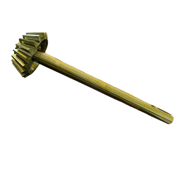
The countershaft (also called the intermediate shaft) is a critical transmission component in cone crushers, serving as a bridge between the power source (e.g., motor via pulley) and the main crushing mechanism. Its primary function is to transfer rotational power from the input pulley to the bevel gear set, which then drives the eccentric shaft to realize the oscillating motion of the moving cone for crushing materials. It also helps stabilize the transmission ratio and distribute torque evenly, ensuring smooth and efficient power transmission under heavy loads.
The countershaft assembly is a multi-part structure designed to withstand high torque and radial/axial forces, consisting of the following core components:
Countershaft Body: A cylindrical or stepped shaft made of high-strength alloy steel (e.g., 40Cr or 42CrMo). Its surface is precision-machined, with key sections for mounting gears and bearings. The shaft length and diameter vary by crusher model, matching the transmission layout.
Bevel Gear (Pinion): Affixed to one end of the countershaft, it meshes with the larger bevel gear on the eccentric shaft to transmit power at a specific gear ratio (typically 1:3–1:5). The gear teeth are precision-cut (helical or straight) to ensure smooth meshing and reduce noise, with a hardened surface (58–62 HRC) for wear resistance.
Pulley Hub: Located at the opposite end of the bevel gear, it connects to the input pulley via a keyway or interference fit. The hub is designed to withstand the tension from the drive belt and transfer rotational force to the shaft.
Bearing Seats: Cylindrical sections on the countershaft where bearings (e.g., tapered roller bearings or spherical roller bearings) are mounted. These sections have strict dimensional tolerances to ensure proper fit with bearings, maintaining shaft coaxiality during rotation.
Keyways and Splines: Grooves or ridges machined into the shaft for securing gears, pulleys, or hubs via keys or splined connections, preventing relative rotation between components.
Lubrication Holes: Small drilled holes running through the shaft to deliver lubricant to bearing contact points, reducing friction and heat buildup during operation.
While the countershaft body is typically forged, the bevel gear and pulley hub (if cast) undergo the following casting process:
Material Selection: Choose low-alloy cast steel (e.g., ZG35CrMo) for gears, as it offers high tensile strength (≥785 MPa) and toughness, suitable for withstanding impact loads. For hubs, gray cast iron (HT300) may be used for its good machinability and cost-effectiveness.
Pattern Making: Create wooden or metal patterns replicating the gear/hub geometry, including teeth profiles (for gears) and mounting features. Patterns include shrinkage allowances (1–2% for steel) to compensate for post-casting contraction.
Molding: Use resin-bonded sand molds for high precision. For gears, the mold cavity must accurately replicate tooth contours to minimize post-casting machining. Cores are used to form internal bores or hollow sections.
Melting and Pouring: Melt the alloy steel in an electric arc furnace, adjusting chemical composition (e.g., carbon: 0.32–0.40%, chromium: 0.80–1.10%) to meet standards. Pour molten steel into the mold at 1520–1580°C, using a bottom-pouring system to avoid turbulence and inclusions.
Cooling and Shakeout: Allow the casting to cool slowly in the mold to reduce internal stress, then remove sand via vibration. Cut off risers and gates using plasma cutting.
Heat Treatment: For gears, normalize at 860–900°C (air-cooled) to refine grains, followed by quenching (850–880°C, oil-cooled) and tempering (550–600°C) to achieve hardness of 220–250 HBW (for machining) before final hardening.
Casting Inspection: Check for surface defects (cracks, porosity) via visual inspection. Use ultrasonic testing (UT) to detect internal flaws, ensuring no defects larger than φ2 mm in critical areas (e.g., gear teeth roots).
The countershaft assembly requires precision machining across components:
Countershaft Body Machining:
Forging: Heat 42CrMo alloy steel billets to 1100–1200°C, forge into rough shaft shapes, then normalize to relieve stress.
Rough Turning: Use CNC lathes to machine outer diameters, end faces, and keyways, leaving 1–2 mm finishing allowance.
Heat Treatment: Quench and temper to achieve hardness of 28–32 HRC for strength, followed by stress relief annealing.
Finish Turning and Grinding: Precision grind bearing seats and journal surfaces to achieve IT6 tolerance, surface roughness Ra0.8–1.6 μm, and coaxiality ≤0.01 mm/m. Drill and tap lubrication holes, ensuring smooth internal passages.
Bevel Gear Machining:
Rough Cutting: Use gear hobbing or shaping machines to rough-cut teeth, leaving 0.3–0.5 mm allowance for finishing.
Heat Treatment: Carburize teeth surfaces (depth 1.2–1.8 mm) and quench to 58–62 HRC, with the core remaining at 30–35 HRC for toughness.
Finish Grinding: Grind tooth flanks using bevel gear grinders to achieve AGMA 10–12 accuracy, ensuring precise meshing with the eccentric shaft gear.
Assembly:
Press-fit the bevel gear and pulley hub onto the countershaft via interference fit (achieved by heating the gear/hub or cooling the shaft).
Secure components with keys or set screws, verifying torque resistance via pull tests.
Mount bearings onto bearing seats, ensuring proper clearance (0.02–0.05 mm) for thermal expansion.
Material Validation: Test raw materials via spectrometry to confirm alloy composition (e.g., chromium, molybdenum content in 42CrMo). Conduct tensile and impact tests to verify mechanical properties.
Dimensional Accuracy Checks:
Use coordinate measuring machines (CMM) to inspect shaft diameter, bearing seat runout, and gear tooth profile.
Verify keyway dimensions (width, depth) with gauges, ensuring tolerance ±0.02 mm.
Surface and Structural Integrity:
Inspect for cracks in the shaft and gear teeth using magnetic particle testing (MPT) or dye penetrant testing (DPT).
Measure surface roughness of bearing seats and gear teeth with a profilometer, requiring Ra ≤1.6 μm.
Functional Testing:
Perform dynamic balance tests on the assembled countershaft to ensure vibration ≤0.1 mm/s at rated speed.
Conduct gear meshing tests to check for noise, backlash (0.1–0.3 mm), and load distribution under simulated operating conditions.
Lubrication System Verification: Test lubricant flow through internal holes to ensure all bearing contact points receive adequate lubrication.
By adhering to these manufacturing and quality control processes, the countershaft ensures reliable power transmission in cone crushers, even under heavy and continuous operating conditions