The lubrication system is a vital auxiliary component in cone crushers, responsible for reducing friction, dissipating heat, and preventing wear between moving parts (such as the main shaft, eccentric bushing, countershaft bearings, and gear meshing surfaces). By continuously supplying lubricants (oil or grease), it minimizes metal-to-metal contact, extends component service life, and ensures the crusher operates smoothly under high-load and high-speed conditions. A well-functioning lubrication system also protects against corrosion and removes debris, maintaining the equipment’s operational efficiency.
The lubrication system for cone crushers is typically a forced oil circulation system, consisting of the following core components:
Oil Tank (Reservoir): Stores the lubricating oil, with a capacity matching the crusher size (ranging from 50 to 500 liters). It is equipped with a sight glass to monitor oil levels and a drain valve for oil replacement. The tank’s inner surface is often coated with anti-corrosion paint to prevent oil contamination.
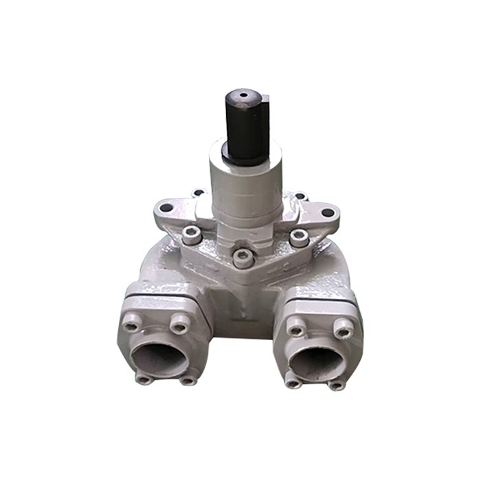
Oil Pump: The power source for oil circulation, usually a gear pump or vane pump, capable of delivering oil at a pressure of 0.3–0.6 MPa. It is driven by an electric motor or connected to the crusher’s main drive via a belt.
Filtering System: Includes a suction filter (coarse filtration, 100–200 μm) at the pump inlet to remove large particles, and a pressure filter (fine filtration, 10–25 μm) in the oil line to trap small contaminants. Some systems add a bypass filter for continuous purification during operation.
Cooling Device: Lowers oil temperature to prevent degradation (ideal operating temperature: 40–60°C). It may be a water-cooled heat exchanger (with a radiator and fan) or an air-cooled cooler, integrated into the oil circulation line.
Distribution Manifold: A network of pipes, hoses, and valves that distributes oil to critical lubrication points (e.g., bearings, gear meshes). Each branch is equipped with a flow meter or pressure gauge to monitor oil supply.
Pressure Relief Valve: Protects the system from overpressure by diverting excess oil back to the tank when pressure exceeds the set limit (typically 0.8 MPa).
Sensors and Monitoring Devices: Include temperature sensors (to alarm if oil overheats), pressure switches (to shut down the crusher if pressure drops), and oil quality sensors (for detecting contamination).
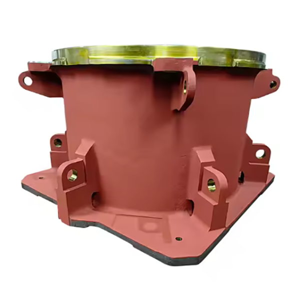
Key cast components like the oil tank and pump housing are manufactured as follows:
Material Selection:
Oil tank: Mild steel (Q235) or cast iron (HT200) for structural strength and weldability (for steel tanks).
Pump housing: Gray cast iron (HT250) for its good machinability and ability to dampen vibrations, ensuring quiet pump operation.
Pattern Making: Create wooden or foam patterns for the tank and housing, including features like flanges, ports, and internal baffles (to prevent oil sloshing in tanks). Patterns include draft angles (1–3°) for easy mold removal.
Molding: Use green sand molds for large tanks or resin sand for precision pump housings. Cores are inserted to form internal cavities (e.g., pump chambers, oil passages).
Melting and Pouring:
For cast iron: Melt in a cupola furnace at 1380–1450°C, adjusting carbon content to 3.0–3.5% for fluidity.
Pour molten metal into molds at a controlled rate to avoid porosity, with risers added to compensate for shrinkage.
Cooling and Cleaning: Allow castings to cool to room temperature, then remove sand via shot blasting. Cut off risers and grind rough edges.
Heat Treatment: For pump housings, stress relief annealing (550–600°C for 2 hours) is performed to reduce internal stress and prevent machining distortion.
Casting Inspection: Check for cracks, blowholes, or incomplete filling via visual inspection and dye penetrant testing (DPT). Use ultrasonic testing (UT) on pressure-bearing areas (e.g., pump housing walls).
Oil Tank Fabrication:
For steel tanks: Cut plates to size, roll into cylindrical or rectangular shapes, and weld seams (using MIG welding). Flanges and ports are welded on, then ground smooth.
For cast tanks: Machine mounting surfaces and ports to ensure flatness (≤0.1 mm/m) and thread accuracy (e.g., G1/2 BSP for connections).
Pump Housing Machining:
Rough turning: Machine outer surfaces, inlet/outlet ports, and bearing seats, leaving 1–1.5 mm finishing allowance.
Finish machining: Precision bore the pump chamber and bearing bores to IT7 tolerance, with surface roughness Ra1.6–3.2 μm. Tap ports for fittings and drill oil passages (diameter tolerance ±0.1 mm).
Filter and Valve Manufacturing:
Filter housings are machined from steel or aluminum, with threaded connections for filter cartridges (5–25 μm porosity).
Pressure relief valves: Turn valve bodies from brass or steel, grind valve seats to ensure tight sealing, and assemble with springs and diaphragms.
Assembly:
Connect the oil pump to the motor via a coupling, ensuring alignment (runout ≤0.05 mm).
Install filters, coolers, and valves into the oil line, using hoses with reinforced layers (for high pressure) and secure clamps.
Mount the distribution manifold and connect lubrication points, then flush the system with clean oil to remove debris.
Material Validation: Test steel and cast iron for chemical composition (via spectrometry) and mechanical properties (tensile strength, hardness).
Dimensional Checks:
Use calipers and gauges to verify tank dimensions, port threads, and pump housing bore accuracy.
Check welds for integrity via pressure testing (tanks: 0.2 MPa air pressure for 30 minutes, no leaks).
Performance Testing:
Circulation test: Run the system at rated flow (e.g., 50–200 L/min) to ensure oil reaches all points with stable pressure.
Pressure test: Subject the system to 1.2 times the rated pressure for 1 hour, verifying no leaks or component deformation.
Cooling efficiency test: Measure oil temperature before and after the cooler (temperature drop should meet design specs, e.g., ≥15°C).
Safety and Reliability:
Test pressure relief valves to confirm they open at the set pressure (±5%).
Calibrate sensors (temperature, pressure) to ensure accurate alarms and shutdowns.
Cleanliness Verification: Analyze oil samples after flushing to ensure particle count meets ISO 18/15 (≤1300 particles ≥4 μm per mL).
By adhering to these processes, the lubrication system ensures consistent, reliable protection for cone crusher components, minimizing downtime and extending equipment life
1. Suitable working temperature
During the working process of the cone crusher, the oil temperature should be kept within the range of 38-55 degrees, and it is not allowed to work in an environment above 60 degrees or below 16 degrees. In the actual production process, a thermometer can be used to measure the oil temperature in the oil return pipeline.
If it exceeds 28 degrees, attention should be paid to it, because it may cause the cone crusher to burn bush.
2. Reasonable work pressure
When the lubrication system is working normally, the working pressure of its lubricating oil and cooling water are both 0.18MPa. The exhaust valve of the lubrication system is installed on the transmission shaft frame. The exhaust valve can make the internal pressure of the cone crusher the same as the external atmospheric pressure, which can ensure the smooth discharge of lubricating oil.
3. choose the correct lubricant
The lubricating oil with lower kinematic viscosity can be used in winter, and the lubricating oil with higher kinematic viscosity can be used in summer.
4. the adjustment of oil volume
The adjustment of the lubricating oil volume of the cone crusher is controlled by the pressure adjustment of the safety valve on the lubricating oil station, and the amount of lubricating oil entering the transmission shaft frame of the transmission part is observed and adjusted by the oil flow indicator.
It should be noted that although the oil flow can be observed in the oil flow indicator, there is no guarantee that there must be lubricating oil inside the cone crusher. It is also necessary to observe the oil return amount of the oil return pipe, and appropriately adjust the pressure control valve on the lubrication station to ensure that the lubrication system returns an appropriate volume and ensure the normal operation of the lubrication system.

