1. High-efficiency hydraulic cone crusher Performance characteristics
a. High work efficiency and large processing capacity;
b. The type of crushing cavity can be adjusted, with a wide range of applications and applications
c. Adopting high-efficiency cone crusher, it can be able to crush into medium and fine particles;
d. The whole unit is installed in one piece, which has the advantages of convenience and flexibility.
e. It combines the common advantages of the mobile jaw crusher and the counterattack mobile crusher.
Discharging Opening in Closed Side |
Model | t/h | 6mm | 8mm | 10mm | 13mm | 16mm | 19mm | 22mm | 25mm | 32mm | 38mm | 45mm | 51mm |
HP100 | t/h | 40-50 | 45-55 | 50-65 | 55-75 | 65-85 | 70-90 | 75-99 | 80-105 | 95-135 |
|
|
|
HP200 | t/h |
|
| 85-115 | 115-145 | 135-175 | 145-185 | 155-195 | 165-215 | 185-230 | 205-245 |
|
|
HP300 | t/h |
|
| 110-135 | 145-180 | 175-215 | 195-235 | 215-255 | 225-275 | 245-315 | 295-375 | 345-435 |
|
HP400 | t/h |
|
| 135-170 | 180-225 | 220-275 | 250-315 | 270-340 | 290-365 | 320-425 | 355-485 | 405-555 | 460-625 |
HP500 | t/h |
|
| 170-215 | 225-285 | 275-345 | 315-395 | 340-425 | 360-450 | 400-530 | 440-600 | 505-695 | 575-785 |
HP800 | t/h |
|
| 255-330 | 320-420 | 380-495 | 430-540 | 465-595 | 490-725 | 540-795 | 595-945 | 685-1045 | 780-1195 |
2. high-efficiency hydraulic cone crusher Summary of advantages
a. Unit equipment installation is integrated, the overall coordination is strong, and the layout is reasonable and compact, which saves time and space for on-site construction, improves flexibility, and eliminates a lot of site infrastructure, greatly reducing investment costs.
b. The vehicle-mounted chassis of the unit is relatively high, the width of the vehicle body is smaller than that of the operating semi-trailer, and the turning radius is small, which is convenient for driving in the rugged and harsh road environment of the crushing site. And it is more conducive to entering the construction area.
c. The configured cone crusher can not only properly perform the function of fine crushing, but also can directly produce finished products of medium and fine-grained sand and gravel, with comprehensive functions, which directly reduces the transportation cost of materials. In addition, the extended unit can directly send the crushed materials into the transfer cart, which is convenient for timely transportation.
d. The cone crusher adopts the principle of static pressure, and after secondary vibration isolation. The equipment vibration is small, which is more conducive to installation.
e. The cone crusher has higher crushing efficiency and stable work, which also saves time to a large extent.
f. The equipment configuration is flexible, which can be independently produced by a single unit, or can be combined to work with rough breaking equipment. In addition to supplying power to the unit, the diesel generator set in the unit can also be configured to supply the unit for the process system, which greatly improves the adaptability of the equipment.
g. Mature technology, easy operation and maintenance. The unit configuration equipment has a clear division of labor, which is concise and easy to maintainPerformance characteristics


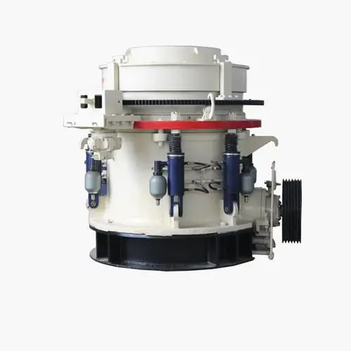
Detailed Introduction to Multi-cylinder Hydraulic Cone Crusher
1. Function and Application of Multi-cylinder Hydraulic Cone Crusher
The multi-cylinder hydraulic cone crusher is an advanced crushing equipment designed for medium to fine crushing of hard and ultra-hard materials, such as granite, basalt, quartzite, and ore. Its core working principle is based on the "lamination crushing" technology: the motor drives the eccentric shaft sleeve to rotate, causing the moving cone to perform periodic oscillating motion. Materials are continuously squeezed, bent, and impacted between the moving cone and the fixed cone (concave), gradually being crushed into uniform particles that meet the required size and are discharged through the discharge port.
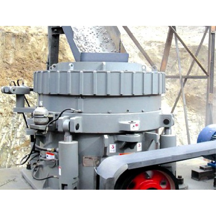
This type of crusher is widely used in mining, construction aggregates, metallurgy, and infrastructure projects. It is particularly suitable for production lines requiring high crushing efficiency, good product particle shape (high cubicity), and large processing capacity, with a typical production capacity ranging from 50 to 2000 tons per hour.
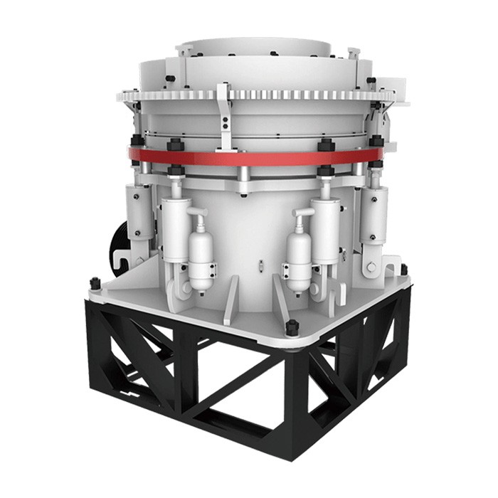
2. Composition and Structure of Multi-cylinder Hydraulic Cone Crusher
The multi-cylinder hydraulic cone crusher consists of several key assemblies, each with specific components and functions:
2.1 Main Frame Assembly
Lower Frame: A heavy-duty cast steel (ZG35CrMo) base that houses the eccentric shaft sleeve, main shaft bearing, and hydraulic cylinder system. It is bolted to the foundation to ensure stability during operation and is equipped with oil passages for lubrication and cooling.
2.2 Crushing Assembly
Moving Cone: A conical component with a wear-resistant liner (high-chromium cast iron Cr20 or manganese steel ZGMn13) attached via zinc alloy casting. The cone body is forged from 42CrMo alloy steel, with a spherical bottom that fits into the main shaft’s spherical bearing to ensure flexible oscillation.
Fixed Cone (Concave): A segmented annular liner (3–6 segments) made of high-chromium cast iron, mounted on the inner wall of the upper frame. Each segment is designed with a specific cavity profile (angle, depth) to control the crushing process and product particle size.
2.3 Transmission Assembly
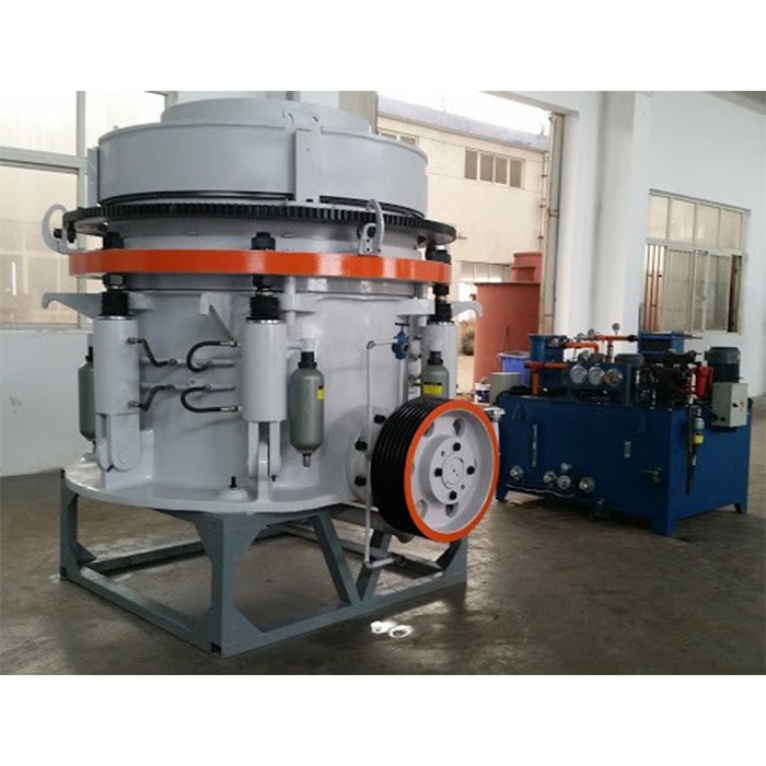
2.4 Hydraulic and Safety System
Multi-cylinder Hydraulic Unit: 6–12 hydraulic cylinders evenly distributed around the lower frame, responsible for adjusting the discharge port size (5–50 mm) and providing overload protection. Each cylinder has a working pressure of 16–25 MPa and is equipped with a pressure sensor for precise control.
Hydraulic Control Cabinet: Contains pumps, valves, and a PLC system to regulate cylinder pressure, enabling automatic adjustment of the discharge port and real-time monitoring of operating parameters.
Safety Relief Device: When uncrushable materials enter the crushing chamber, the hydraulic cylinders automatically retract to expand the discharge port, expelling the foreign matter, then reset to the original position to resume operation.
2.5 Lubrication and Dustproof System
Thin Oil Lubrication System: An independent system with pumps, coolers, and filters that circulates lubricating oil (ISO VG 46) to bearings, gears, and the eccentric sleeve. It maintains oil temperature below 55°C and pressure at 0.2–0.4 MPa.
3. Casting Processes for Key Components
3.1 Upper/Lower Frame (ZG270-500 and ZG35CrMo)
3.2 Eccentric Shaft Sleeve (ZG35CrMo)
Pouring and Heat Treatment: Molten steel is poured at 1500–1540°C. After casting, the sleeve undergoes quenching (850°C, oil-cooled) and tempering (580°C) to achieve hardness HB 220–260 and tensile strength ≥785 MPa.
3.3 Moving Cone Body (42CrMo Forging)
Heat Treatment: Quenching (840°C, water-cooled) and tempering (560°C) to achieve tensile strength ≥900 MPa, yield strength ≥785 MPa, and hardness HRC 28–32.
4. Machining Processes
4.1 Frame Machining
4.2 Eccentric Shaft Sleeve Machining
4.3 Moving Cone Machining
5. Quality Control Processes
The multi-cylinder hydraulic cone crusher’s robust structure, precise manufacturing, and advanced hydraulic control ensure high efficiency, reliability, and excellent product quality, making it a core equipment in modern crushing production lines